0.008 FINAL: 5 Axis Timing Belt MTM
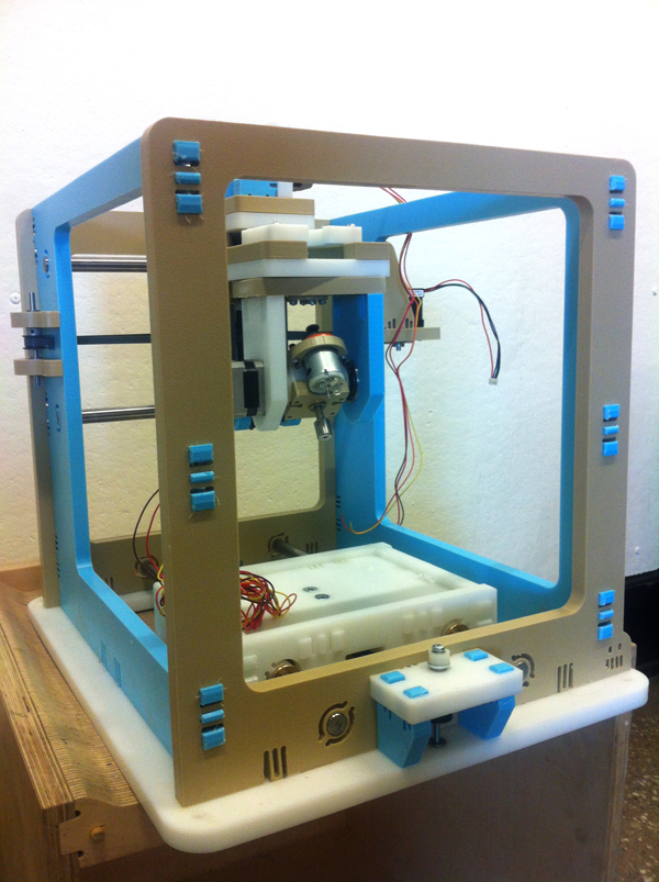
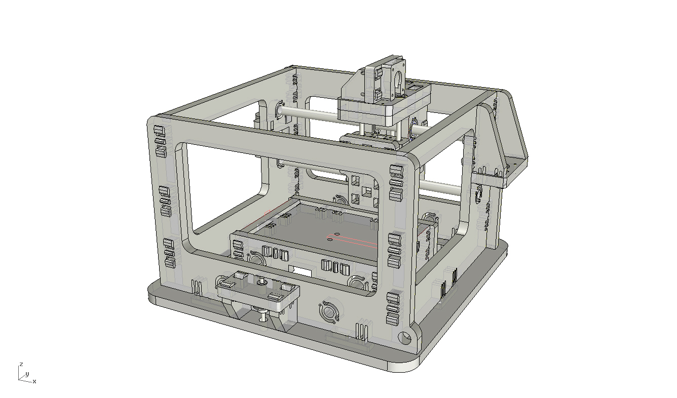
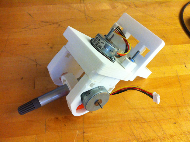
Final Model of MTM
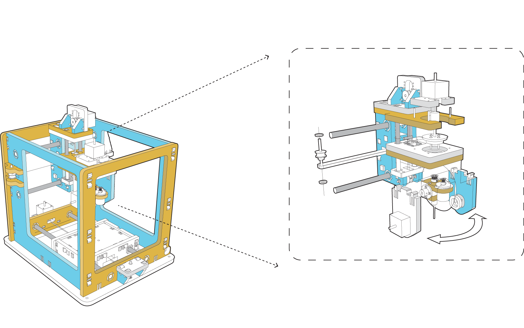
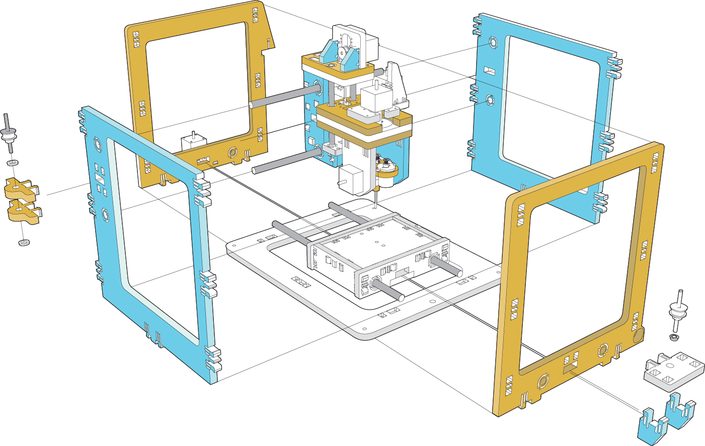
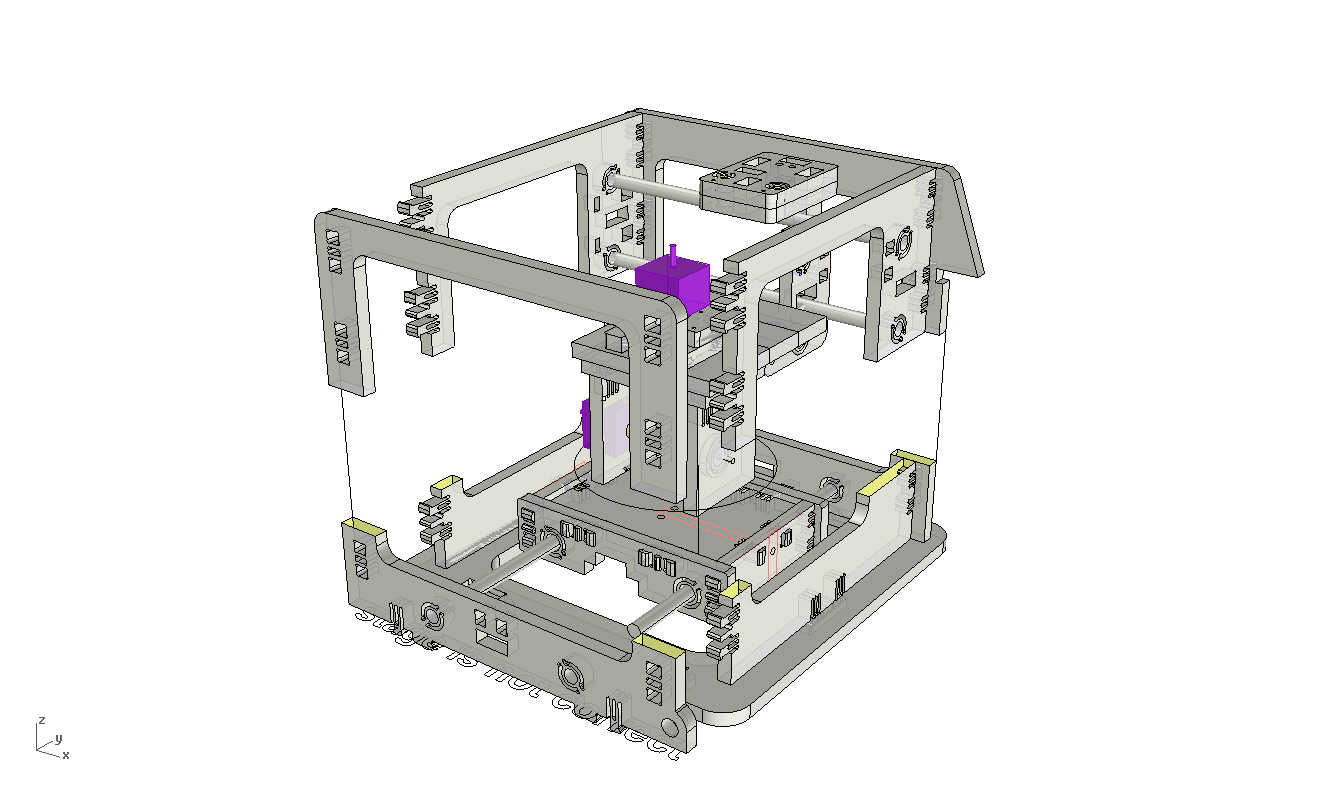
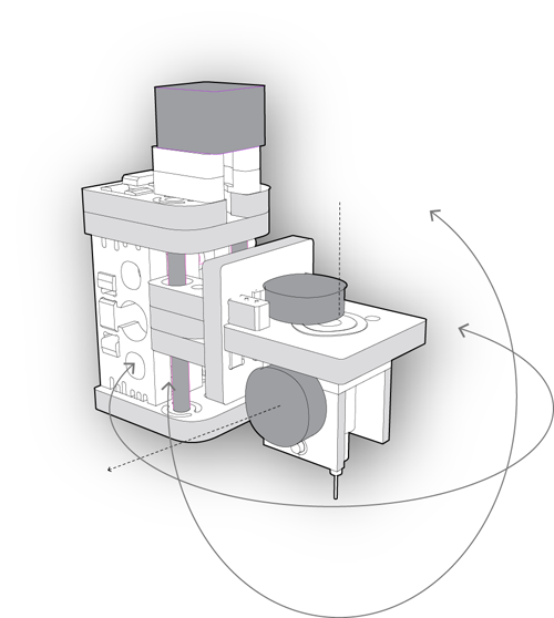
Exploded Model showing component assembly
Snapbelt is expanded to enlarge the working volume of the 5 axis head. Z height 4"
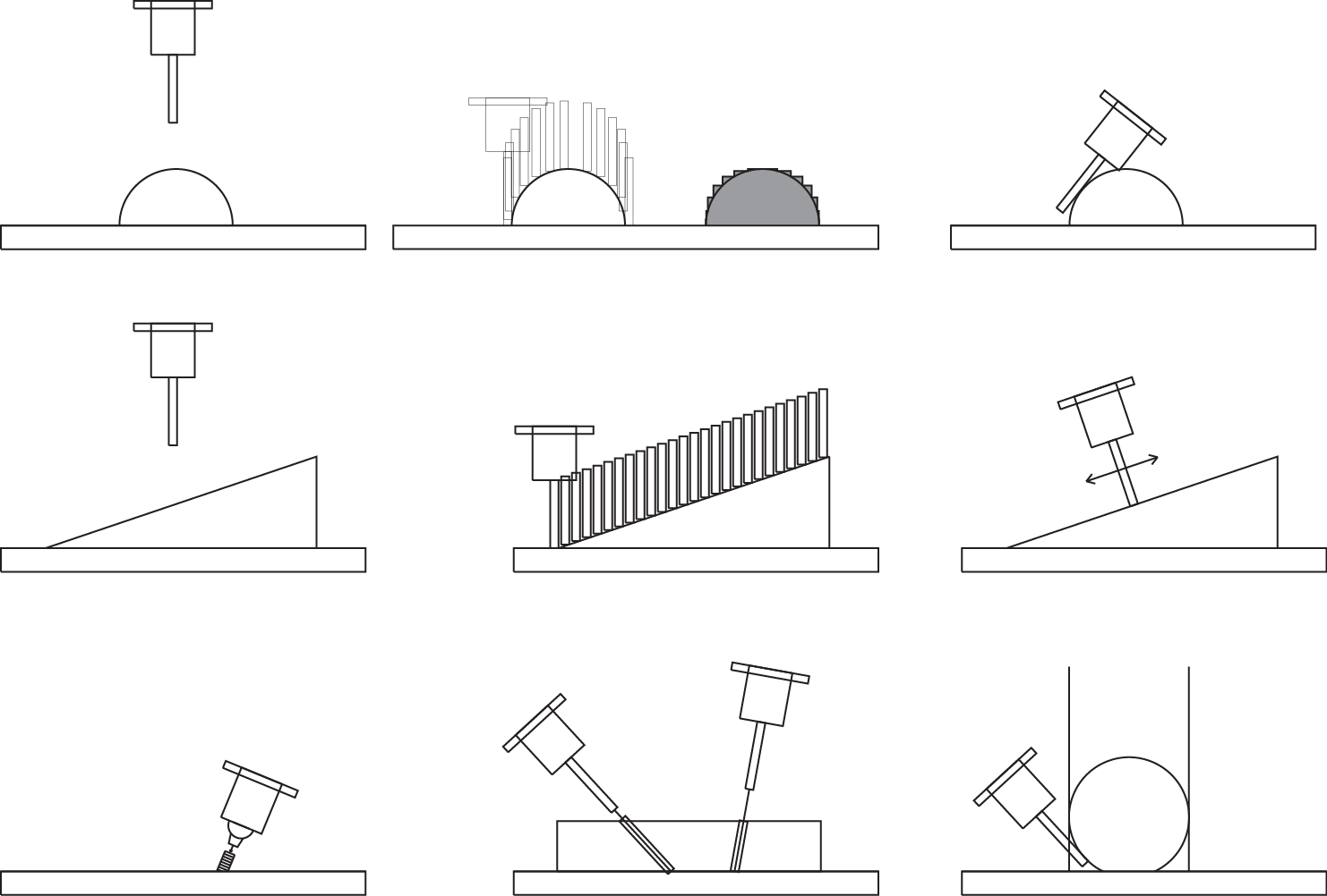
Why 5 Axis?
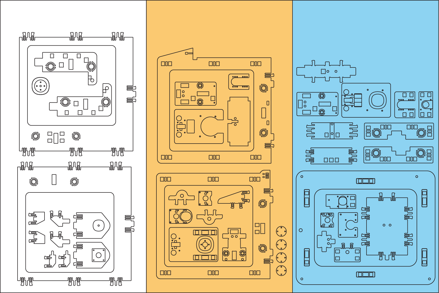
Cut sheets
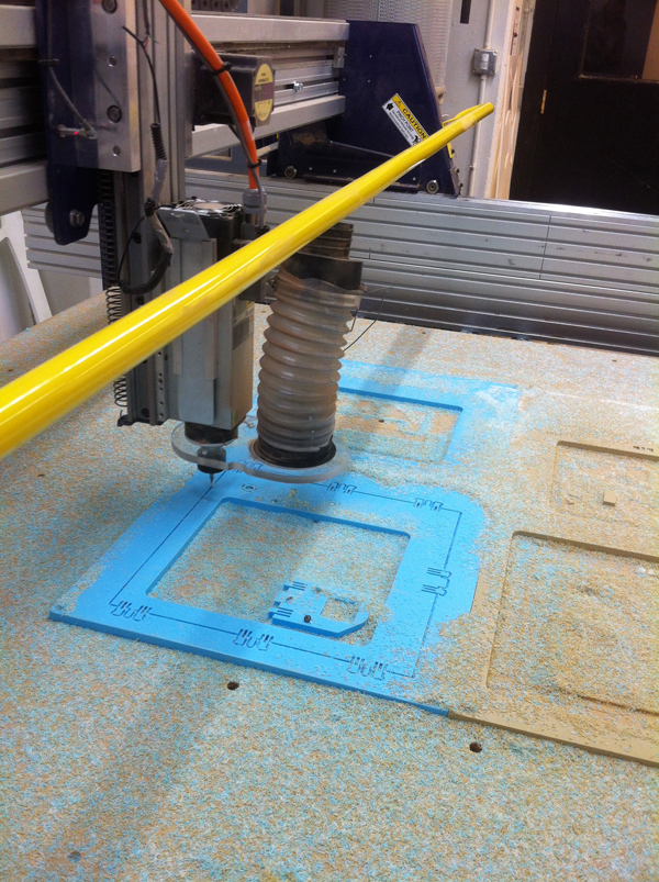
Machining of HDPE
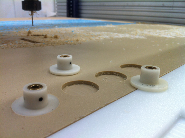
Re machining of shaft flange mounts
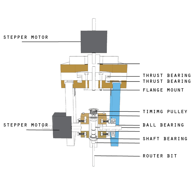
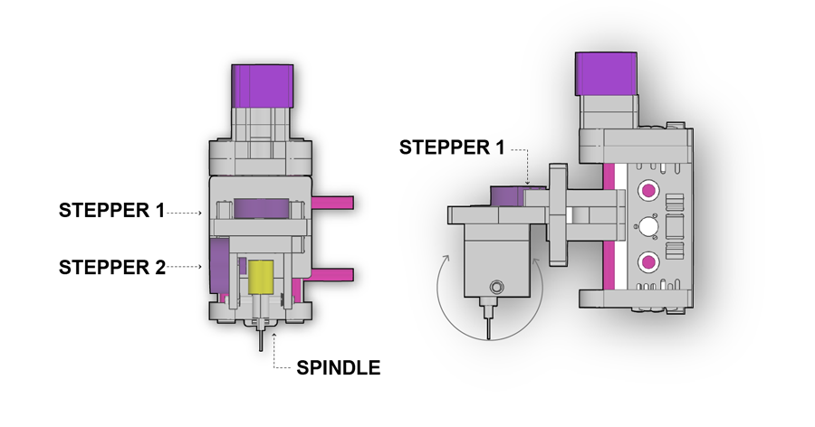
Spindle assembly section
Final Assembly of machine
Decompiling Vector for YAW and PITCH angles
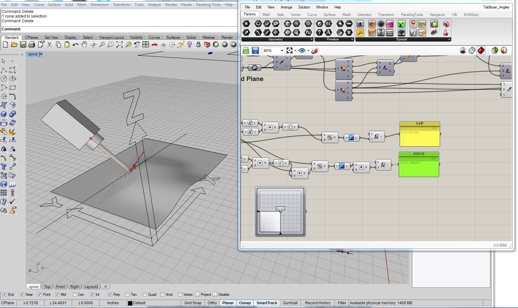
Using Rhino and Grasshopper I decompile the tooling vector in order to extract YAW and PITCH angles that correspond to the 4th and 5th axis
0.007 Time(Belt) to Make:
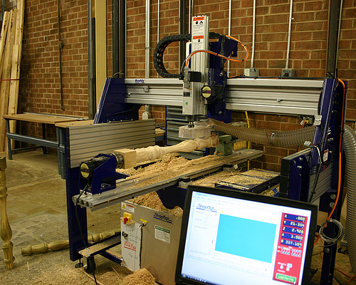
Current model of Jonathon Ward's belt driven MTM
Premodified belt driven MTM
Snapbelt is expanded to enlarge the working volume of the 5 axis head. Z height 4"
0.006 Sizing and Connection
Progess being made on a dettachable spindle attachment. Using Jonathan Ward's MTM as an armature for holding a number of tools.
Milled HDPE prototype one. Next step is specifying bearings and purchase order.
Video describing motion of the prototype 5 Axis head. NOTE a marker is acting as a place holder for spindle assembly.
view of attached mill head. Showing a flat attachment plate that could accomodate a number of tools.
View of attached tool from front and right. Tool stability is a concern in this version!
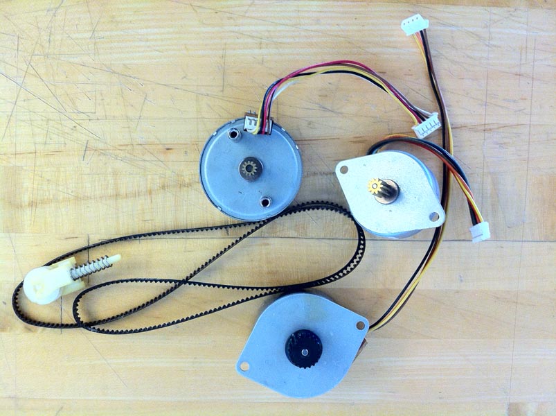
For a first test I plan to construct the draft with reclaimed printer stepper motors.
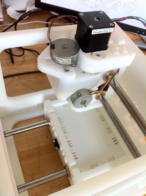
Space planning sketch with printer motors placed on MTM armature.
0.005 5 Axis Sketch 2
Current sketch with a tube section to stabalize the spindle.
Sketch of tube section head. Aluminum and HDPE
Example of a industry "tube section" 5 axis mill head
0.004 5 Axis Sketch
As a point of departure I began with concieving how a multi axis attachment might be incorporated into the Snap MTM axis milling machine. Using the MTM Snap's methods of connection, flexure joints in HDPE, I plan to extend to capabilites of the MTM to 4 + 5 axis milling.
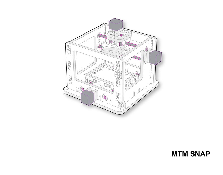
Rebuilt 3d model of MTM Snap machine
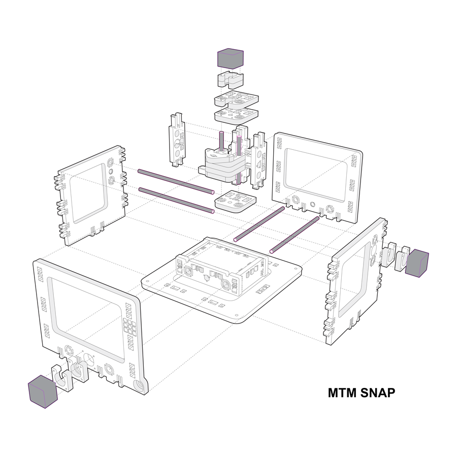
Exploded component view of MTM Snap
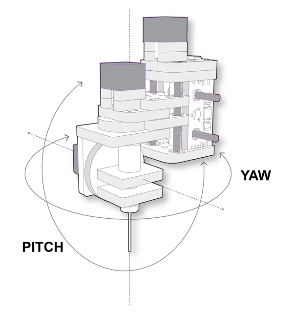
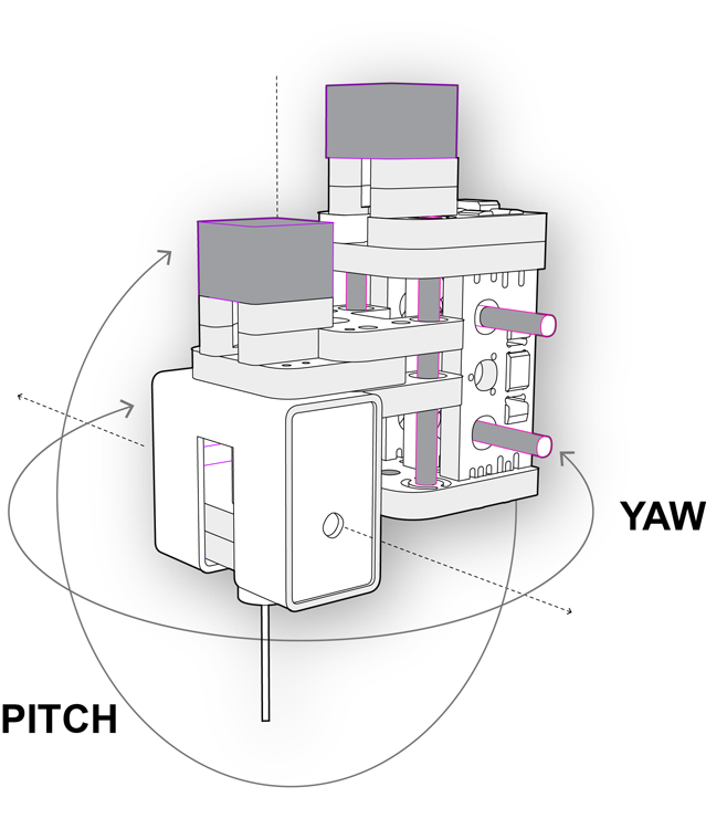
Concept sketch of multi-axis milling head capable of providing Yaw and Pitch orientation. This aproach is seen as preferable over a rotary indexer because of the scale limitations associated with them. The multi axis head will provide a larger work volume and is relatively scalable with increased machine size, unlike the indexer.
Animation of the spindle rotation for 4 and 5 axis
The 4th axis of a Kuka robot is also an area of study I would like to pursue. The main difference between the Kuka setup and my current 5 axis setup is the dependency of Pitch on Yaw. Evaluating the potential benefits of reversing this dependency may yeild work volume freedoms.
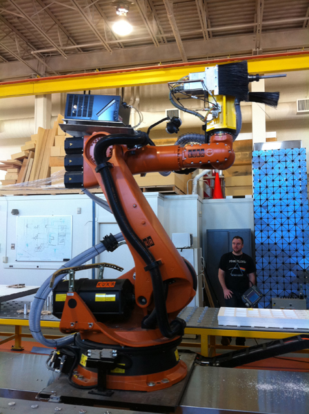
Above is the MIT IDC Kuka 100HA showing the 4th axis described above
0.003 Rotating Spindle
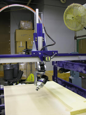
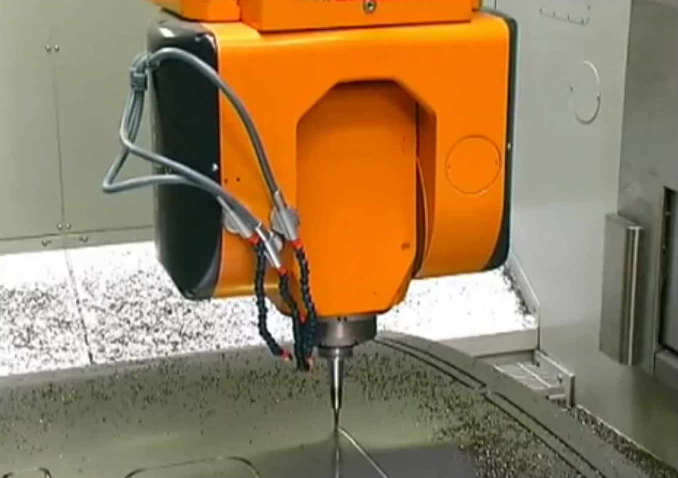
Another possible multi axis addition to a 3 axis machine is articulated milling head. Shopbot has recently released such an addition: "This tool takes advantage of standard ShopBot modular components, adding a 2-axes head on the end of the Z-arm that creates wrist-like movement capabilities. We brought a small version of the tool to the show, but the 5-axis head can be fit to any size PRSalpha ShopBot with an extended Z.
Above is Shopbot's 5 axis mill in action
This option provides the most versatility and the largest work envelope. A rotating head is potentially the best option for large format mills where rotation of the stock would require high torque motors.
0.002 Trunnion Table
Expanding the capabilities of the Rotary Axis is the Trunnion table pictured below. Once again this is an excellent way to improve an existing machine but the working envelope is limited to the extents of the table. Trunnion tables or "tilt rotary" tables allow the rotary indexer to also rotate, such setups can accomplish a number of 5 axis operations.
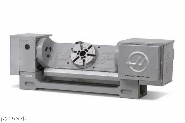
Trunnion table manufactured by HAAS
Above is an example of a trunnion table installed on a vertical mill
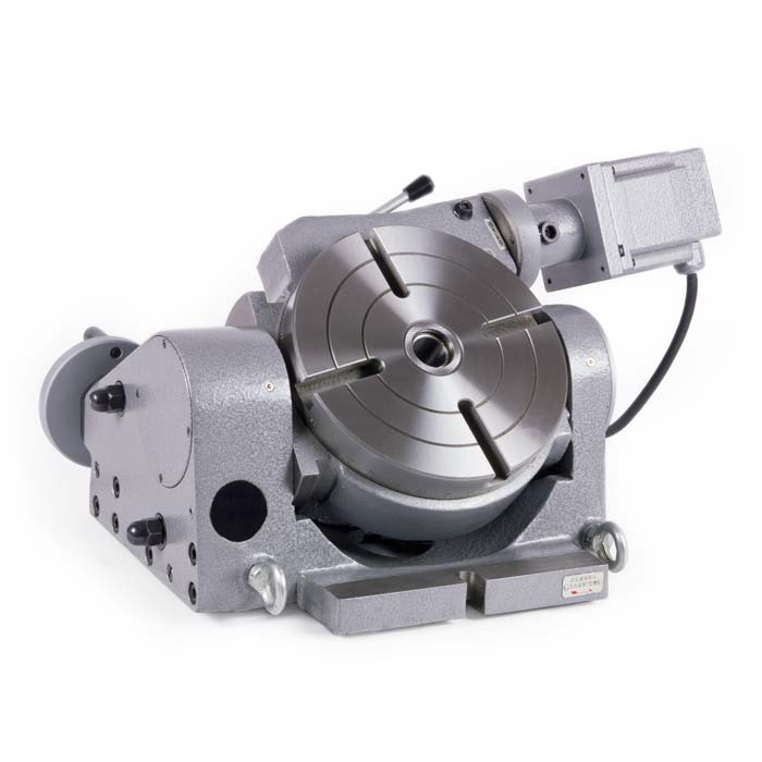
0.001 4 Axis
The capabilities of 3 axis milling machines can be significantly expanded with the addition of either a rotary indexer or trunnion table. A rotary indexer enables 4 axis milling operations, such setups are typically deemed a "3 + 1" axis machines. Pictured below is an example of a Rotary indexer and a large format indexer sold by ShopBot:
The G-Code necessary to control a 3 axis machine requires 4 variables - X,Y,Z (positioning coordinate) A (axis rotation value). EXAMPLE:
The alterations to the current fabmodules necessary to program a rotary indexer would be trivial in comparison to the 5 axis tool pathing.
Above see the mill in action!
Large format rotary indexers are available but require a tail stock holder. This is a fairly inexpensive solution but severely limits the working envelope of the mill.