MAS862, Physics of Information Theory Project Archive
(Completely) mechanical Logic Gates
Pragun Goyal
1. Description
Electronic gates have some really nice properties that help us put a large number of gates together to realize computers, PDAs, etc. However, electronic gates are hidden, in the sense that you cant understand what's going on inside an elelectronic gate by just looking at it. The objective of this project is to design and make a functionally complete set of mechanical gates that have a good set of the following properties.
(Almost) Infinite input impedance
(Almost) Infinite input impedance means we can drive (almost) as many gates from the output of one gate as we want. Basically, allows for infinite fanout. A simple way to think about this is to think about the branching factor in a tree.
Power separate from signal
Separating the power from signal allows (almost) infinite cascadability. Think of this as the depth of a tree.
Unconstrained interconnects
Connecting electronic gates is trivial! All you need is a conductive path from the ouput of one gate to the input of another. There are no serious mechanical constrains on the conductive path, contrast this with gears, pulleys, etc.
2. Prior Art
1. Charles Babbage's Engines
2. Konrad's Z1
3. Pinball game like mechanical counting machines
4. Digicomp
5. Donald Michie's matchbox computer for tic-tac-toe
3. Push/Pull bits
One possible way of representing bits mechanically is the position of a bar. Here's how a simple AND gate can be made using this representation.
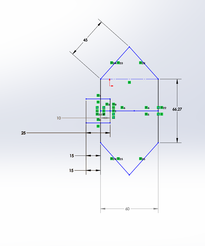
The two horizontal lines marked with dimensions reading 15 are the inputs. The dimension marked 60 is the output.
Here's how it responds to different inputs.
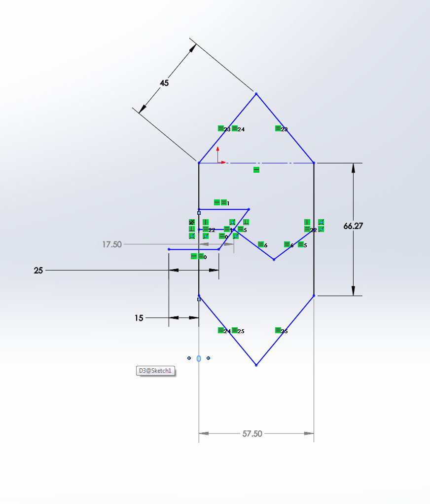
Input: 01: Note how the output reads 57.5, this however can be fixed by changing the length of the connecting bars.
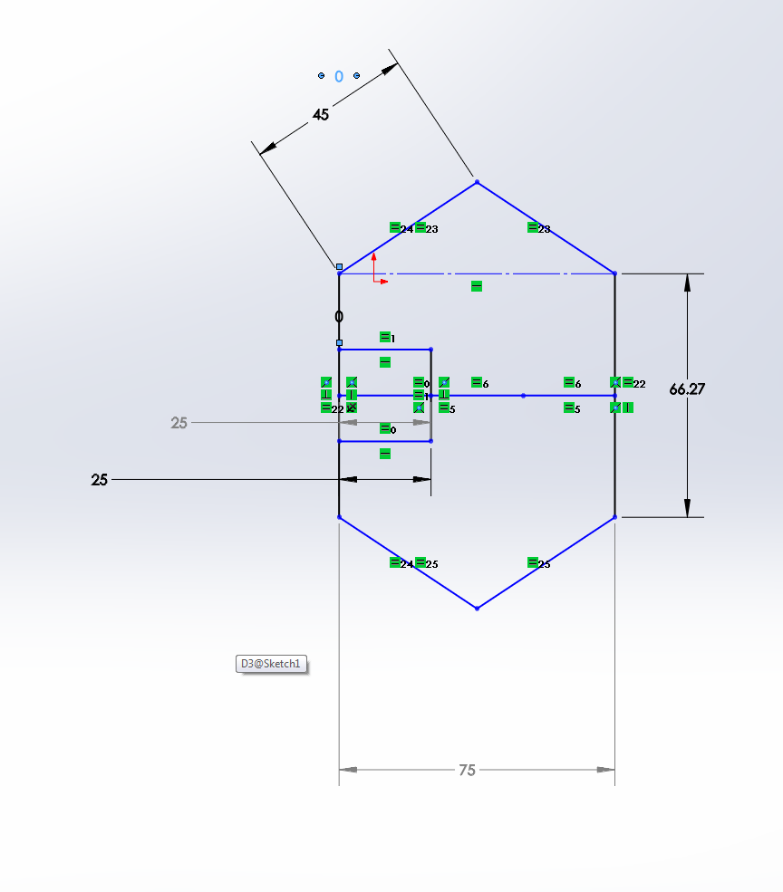
Input: 11
The output, during the transition of input from 00 to 01 goes like this.
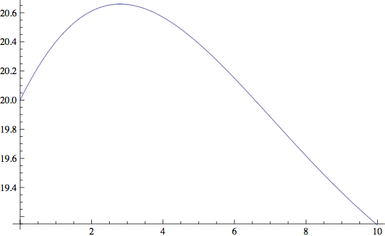
This is how the output responds from a transition from 01 to 11.
Non-linearity, gain
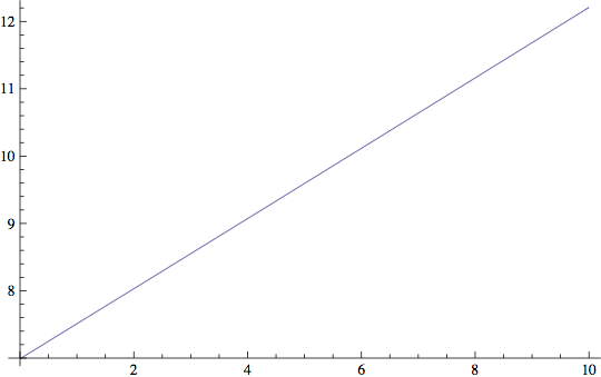
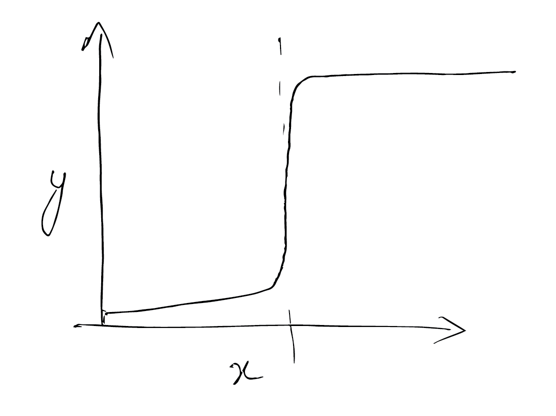
A peice of cardboard, buckled and held in the hand exhibhits bistability! And non linear behaviour as it transitions from one state to another.
Bistable buckled beams, in their simplest forms are not very useful for the purpose of the project as the input (the center of the buckled beam on the left side) is tightly bound to the output (the center of the buckled beam on the right side), but if we introduce a spring between the input and the output, it allows the input to move somewhat independently of the output.
However, springs that have a good compressive and tensile response are somewhat difficult to find.
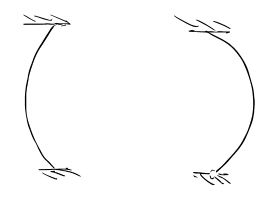
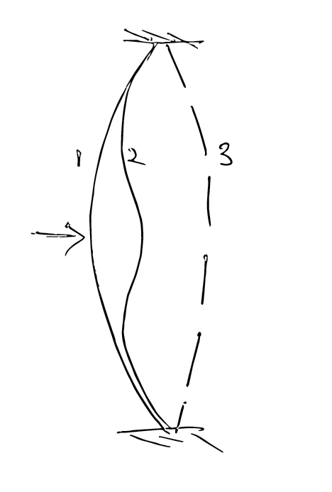
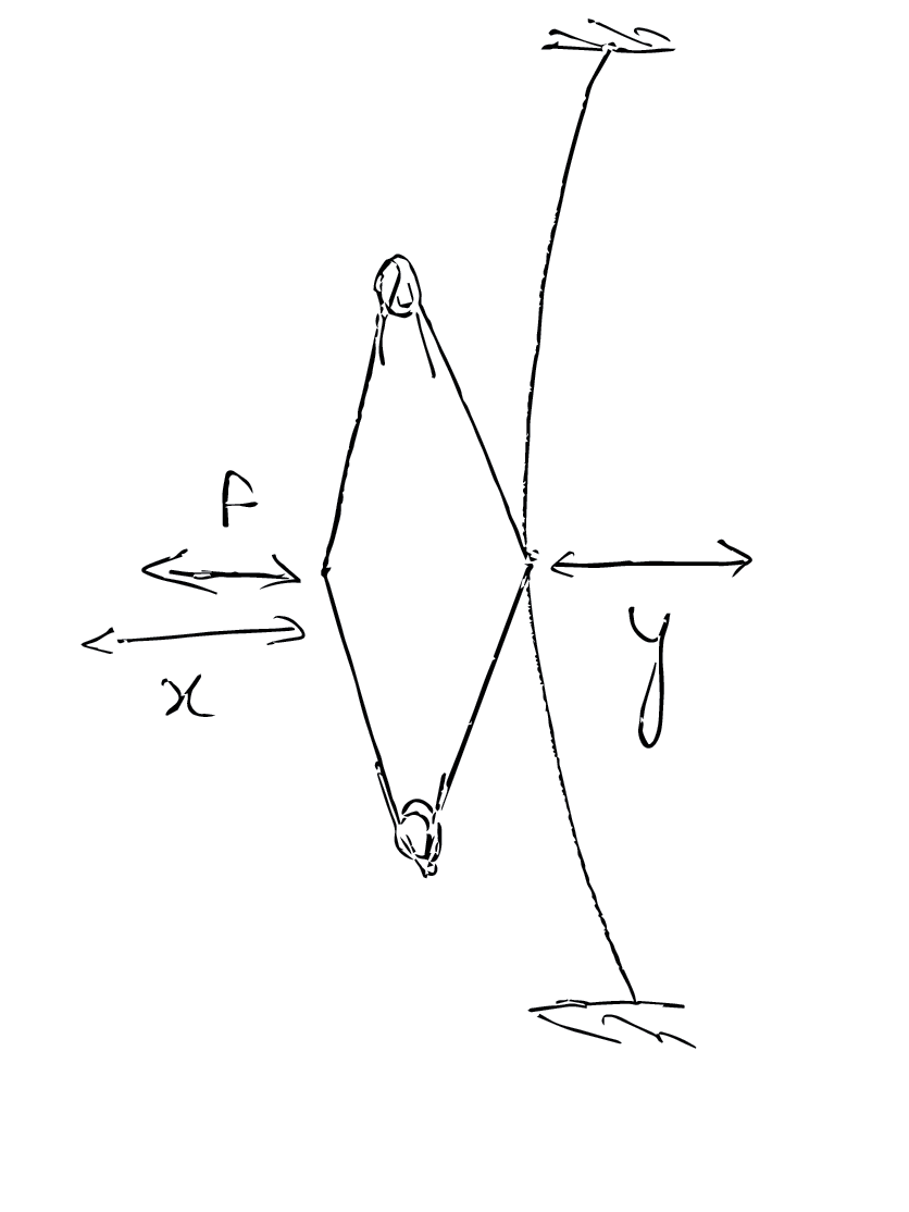
But, a simple four bar linkage with torsion springs mounted on two diagonally opposite corners is as good as a spring with a good compressive and tensile response!
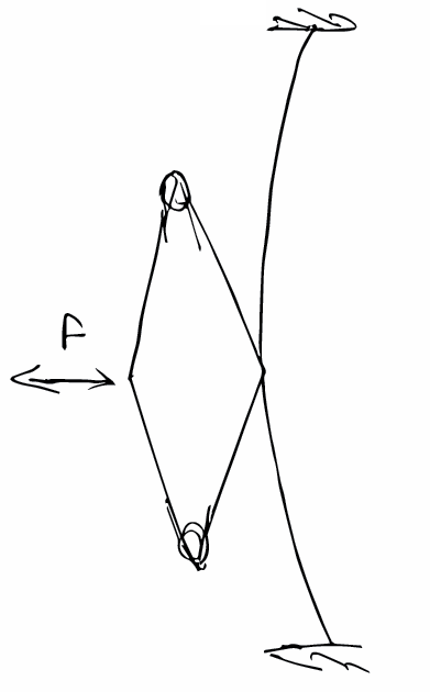
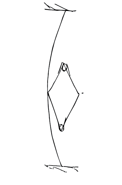
I haven't modelled this yet, but I hope to get something like the following image.
References
Bistable Buckled Beam: Modeling
of Actuating Force and
Experimental Validations
Linear feedback shift register
Building complete digital logic from scratch seems infeasible, so, now, I'm hoping to show a mechanical LFSR. The simplest LFSR would involve a 3-bit shift register fed by the XOR (or any other boolean function) of the values of the bits in the register.
Shift register, flip flops
A shift register can be realized as a series of flip flops connected in series. A flip flop can be thought of as a bistable element that is easy to read and write state from.
Gravity driven gates
In Shaun's binary counter (here), gravity accelerates marbles. When this accelerated marble goes through the gate, the kinetic energy of the marble is used to restore the state. The gate, thus effectively rendered bistable is very similar to a T flip flop, however it is not easy to read from or write to.
Easy to write to read from flip-flop
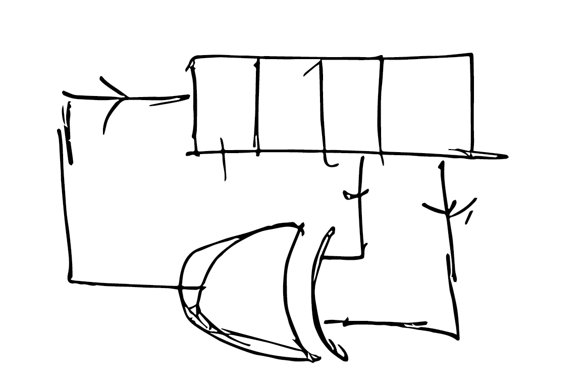
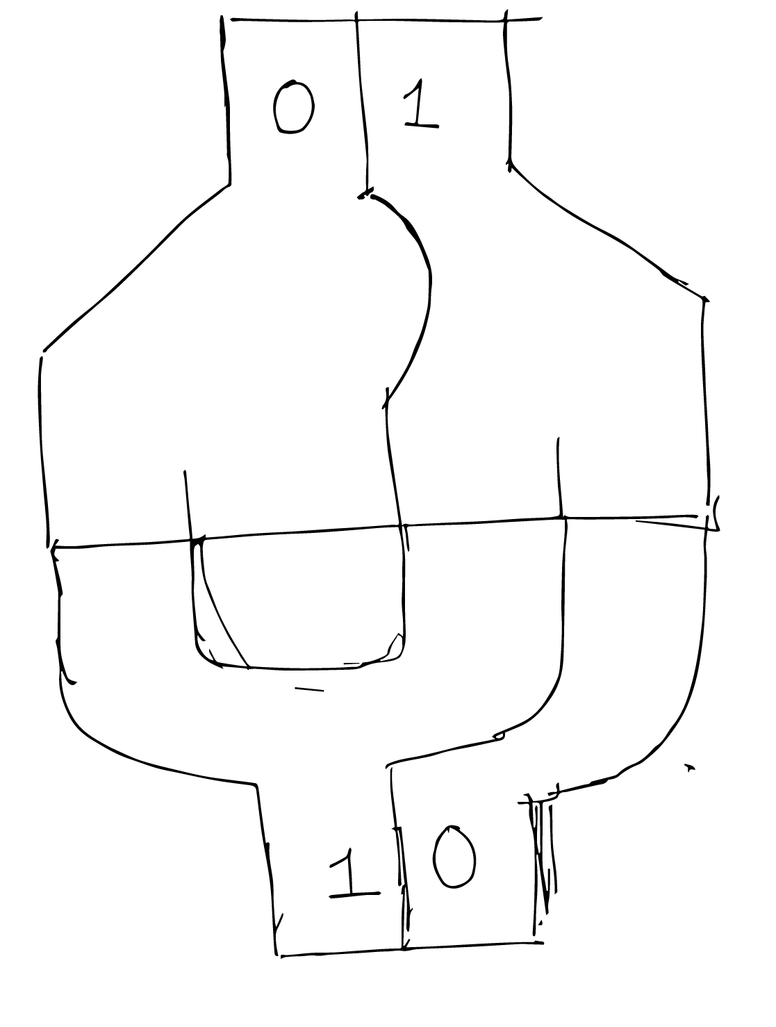
An easy to write to flip-flop would allow itself to be set to any arbitary value. A gate that looked like this, would be easy to set to a value, by choosing one of the input lanes to send the marble along in.
This arrangement also allows for a nice way to read the value of the flip-flop, by looking at which lane the marble came out on.
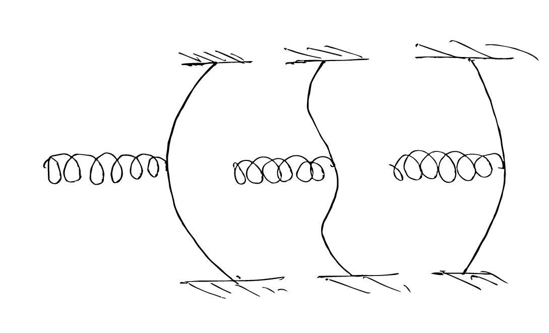
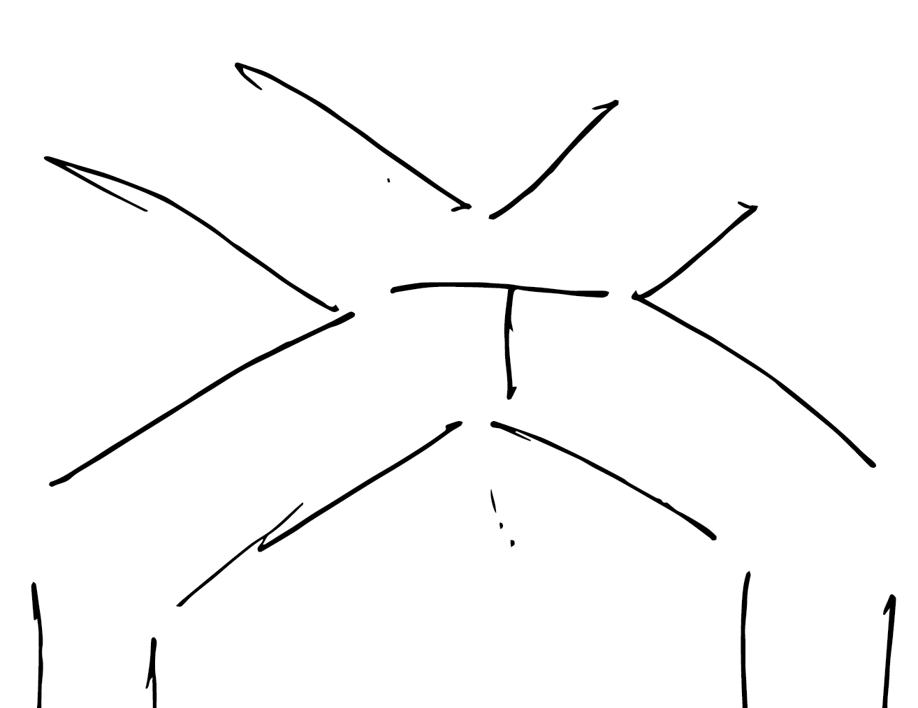
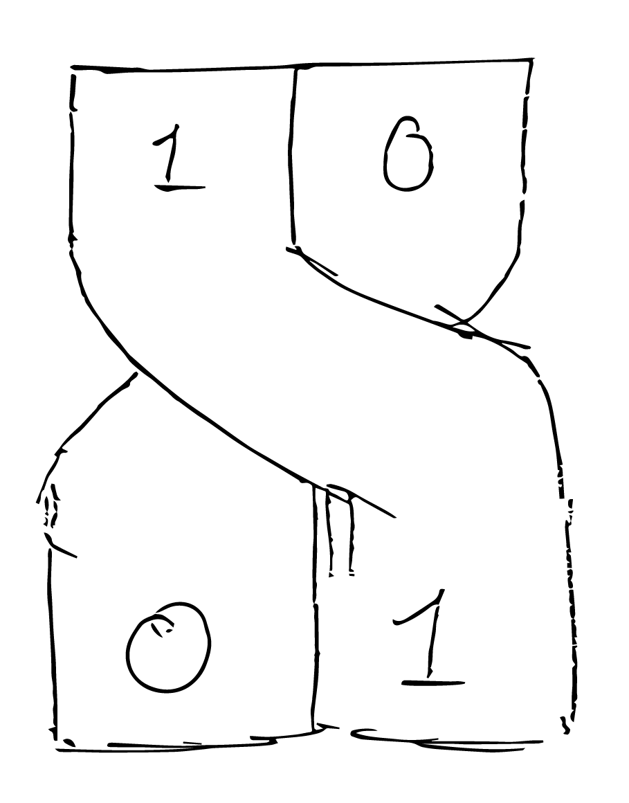
Going through all input and flip-flop state combinations gives something like this,
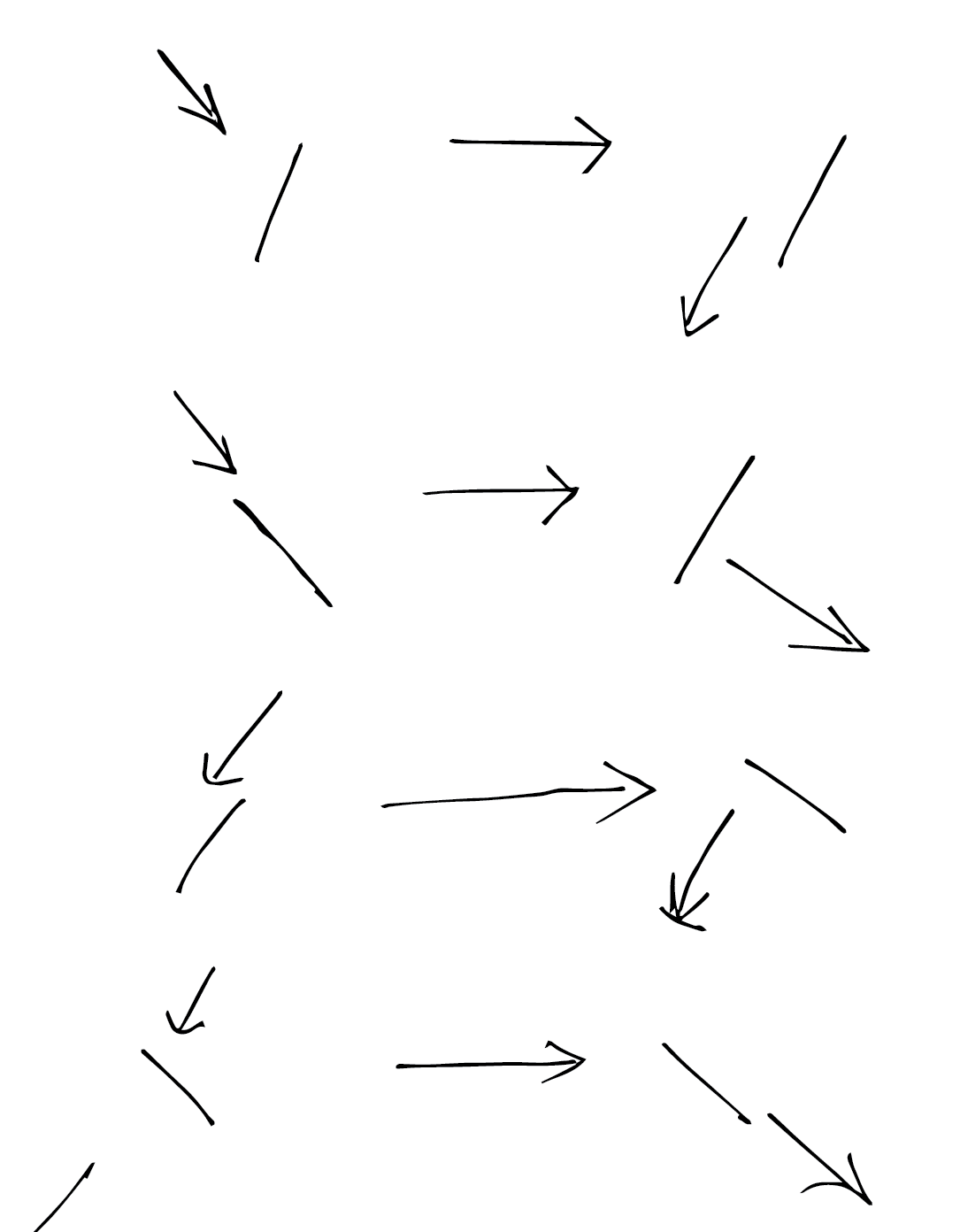
whats interesting about this is that, when the value of the flip-flop is changed, the bistable mechanical element should not only change state but also direct the marble along the path dictated by its original state. I thought about different ways to realize this.
Ultimately, I came back to the buckled beam as the bistable element, as it provided for a very simple implementation of the flip-flop. In my sketch, I introduced a set of rigid flaps that rest on the buckled beam. I was thinking that the flaps would help transfer more kinetic energy from the marble to the buckled beam. But, after I made it, I realized that the flaps are not necessary. The buckled beam by itself works just as fine.
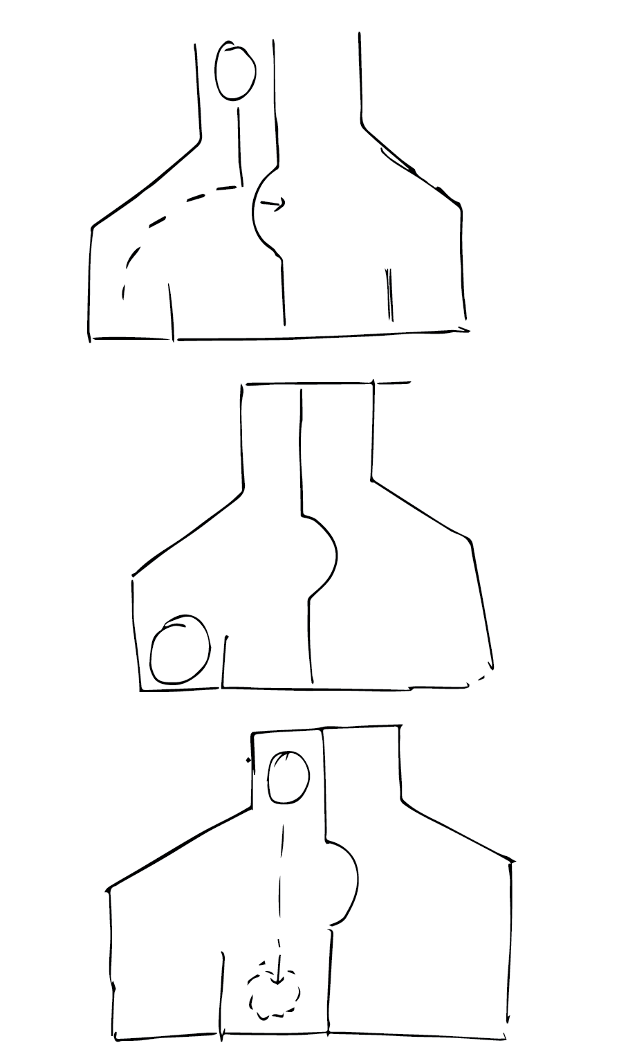
A minor issue with this design is that it creates four outputs, corresponding to the four combinations. But, two outputs can be combined to create an output that can again mate with another flip flop.
This logic representation allows for an extremely trivial NOT gate, created by just twisting the channels around. Infact it is the exact mechanical analog of differential singalling.
Proof of concept
I made a half-flip flop out of acrylic to play around with different materials for the bistable buckle. Ultimately, a strip of paper from my regular sketch book seemed to work just fine.
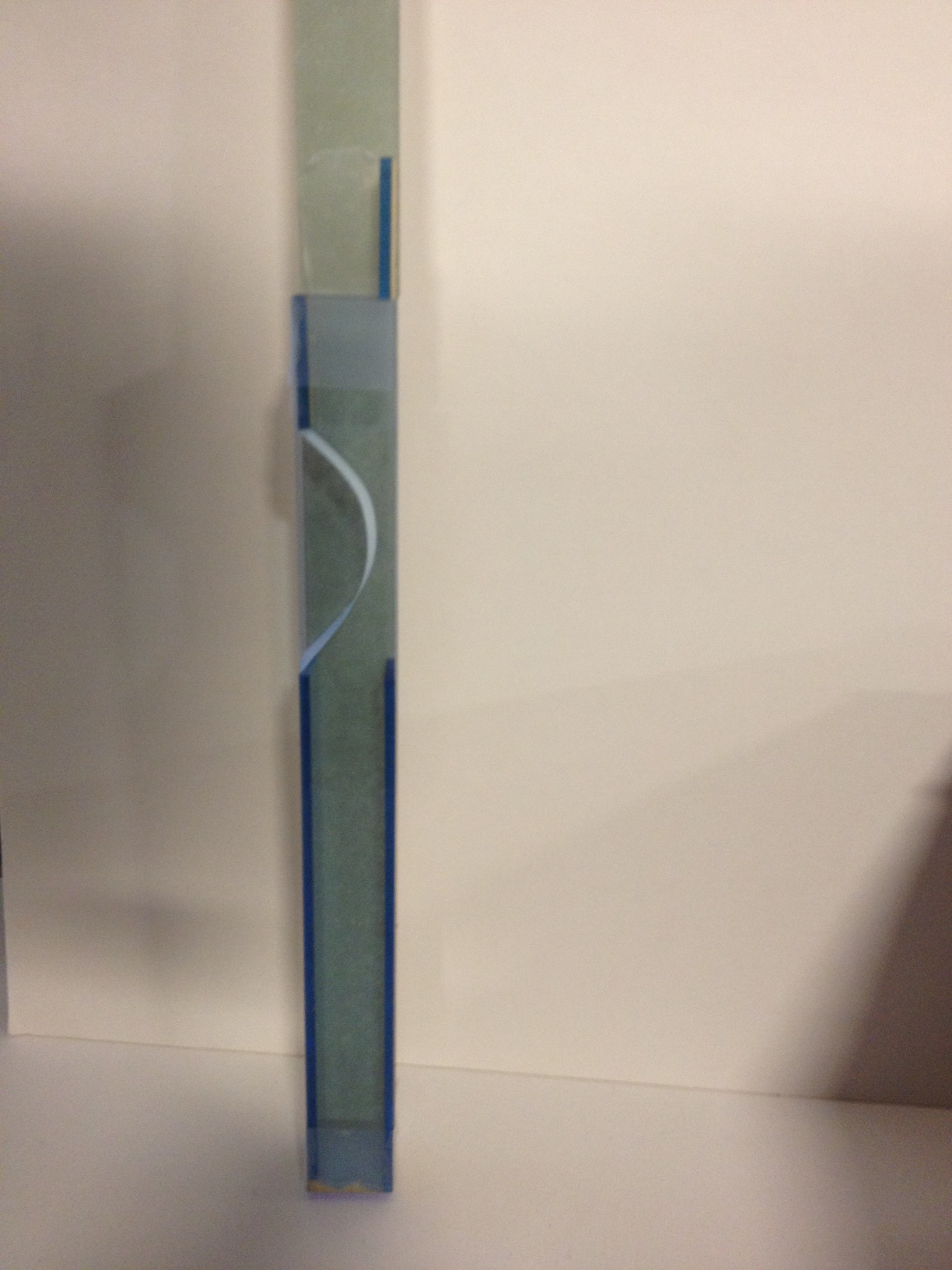
When completed, the flip flop works as shown in the following video.
I made two flip flops and connected them, to see if they work as two-bit shift register. It worked! But, unfortunately one of the flip-flops fell down and broke apart, before I could record a video! :(

Conclusion
The flip-flop design works like a SR latch. The buckled beam provides for non-linearity. Weight of the marble provides gain.
Future work
Complete the logic gate family.