PIT: Discrete Passives
Discrete Capacitor Design
Discrete Inductor Design
Discrete Assembly
Experimental Testing Method
Conclusion and Implications
References
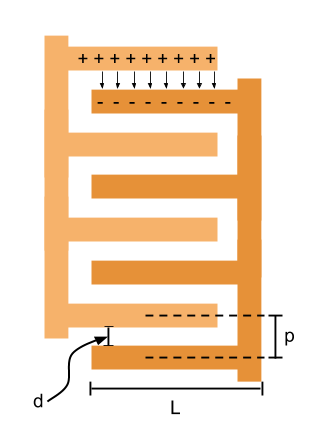
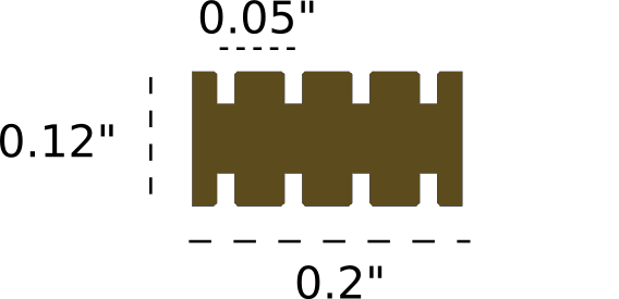
I first thought about what a capacitor made up of discrete parts might look like. I converged on an interdigitated capacitor.
This kind of capacitor makes good use of space and is easily implemented on the lego-gik lattice.
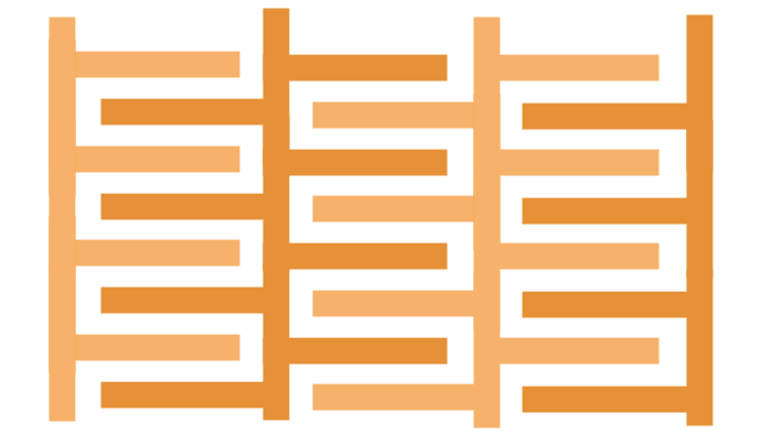
It can also be easily tiled in any dimension (x, y, or z). Here, for example, is a simple tiling in the x and y directions:
The capacitance of a single unit capacitor can be found using the relationship: C = e*A/d. For a unit consisting of 6 conductive parts, this capacitance is roughly 10*e. Notice that because there is a relationship between L and d for the lego-gik, the capacitance per unit scales linearly with the characteristic spacing of the parts (d). However, because volume decreases with the cube of the characteristic spacing, there are large wins in efficiency when scaling down.
To create a 1uF capacitor requires on the order of 10 million parts.
To create a 1nF capacitor requires on the order of 10 thousand parts.
To create a 1pF capacitor requires on the order of 10 parts.
This suggests that I may strive to create a capaictance in the pF to nF range given that it would only be feasible to put together a discrete capacitor with order 10 parts by hand.
I spent quite some time trying to come up with an efficient way to make an inductor from the lego gik parts but ultimately settled on a really inefficient design.
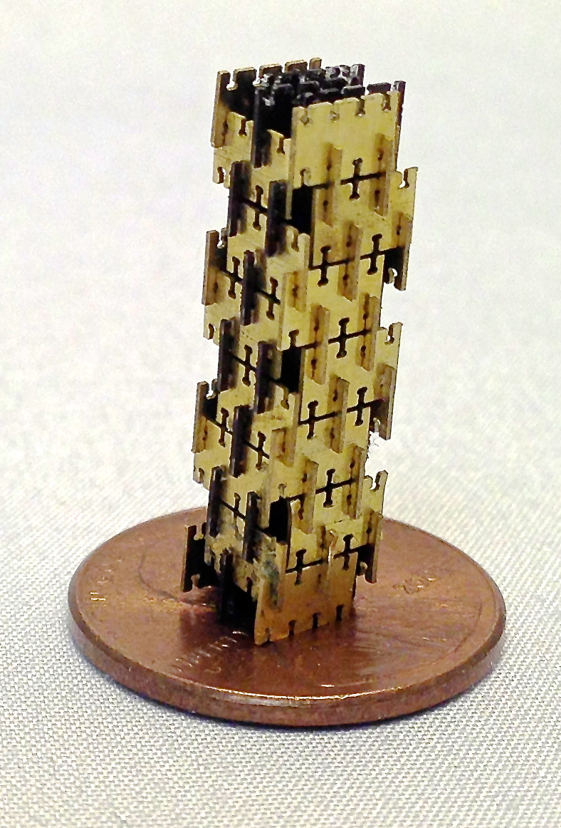
The final design I chose to pursue is simply a vertical coil for which it completes 1 turn every 4 vertical layers.
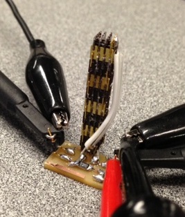
The devices are small enough to be fairly easy to assembly by hand. It took on the order of an hour to assemble both capacitor and inductor.
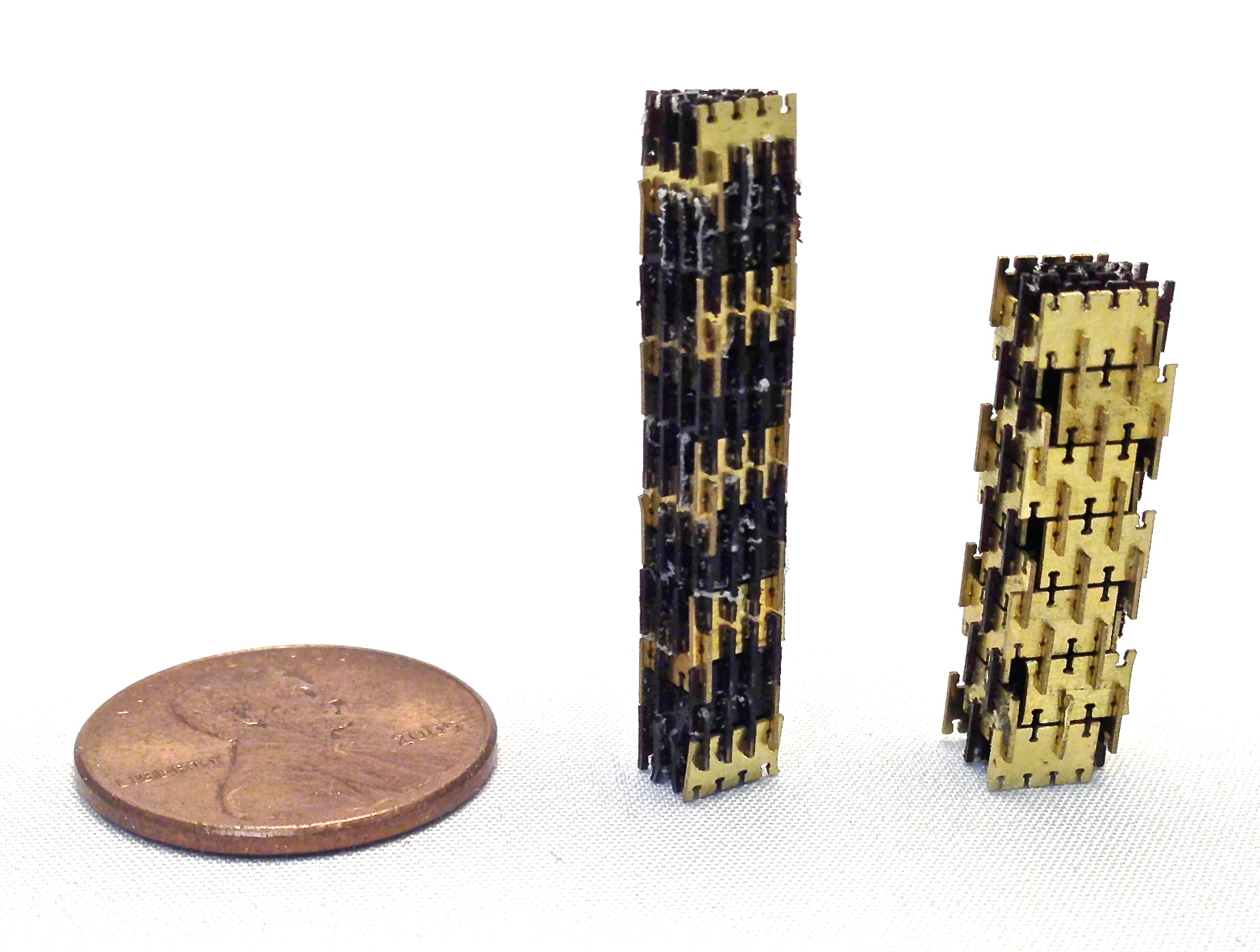
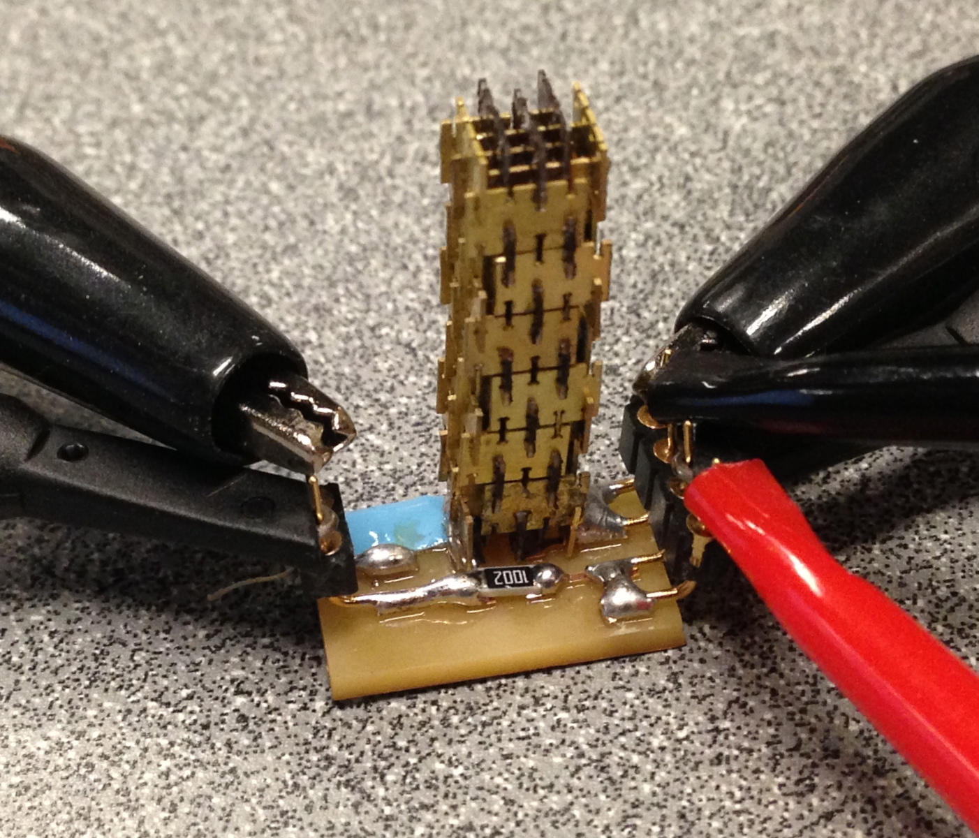
I assembled the devices by hand (and with tweezers).
I used two different methods to test the devices:
I first used David Mellis' Capmeter Board to see if it could measure capacitances in the 1pF range.

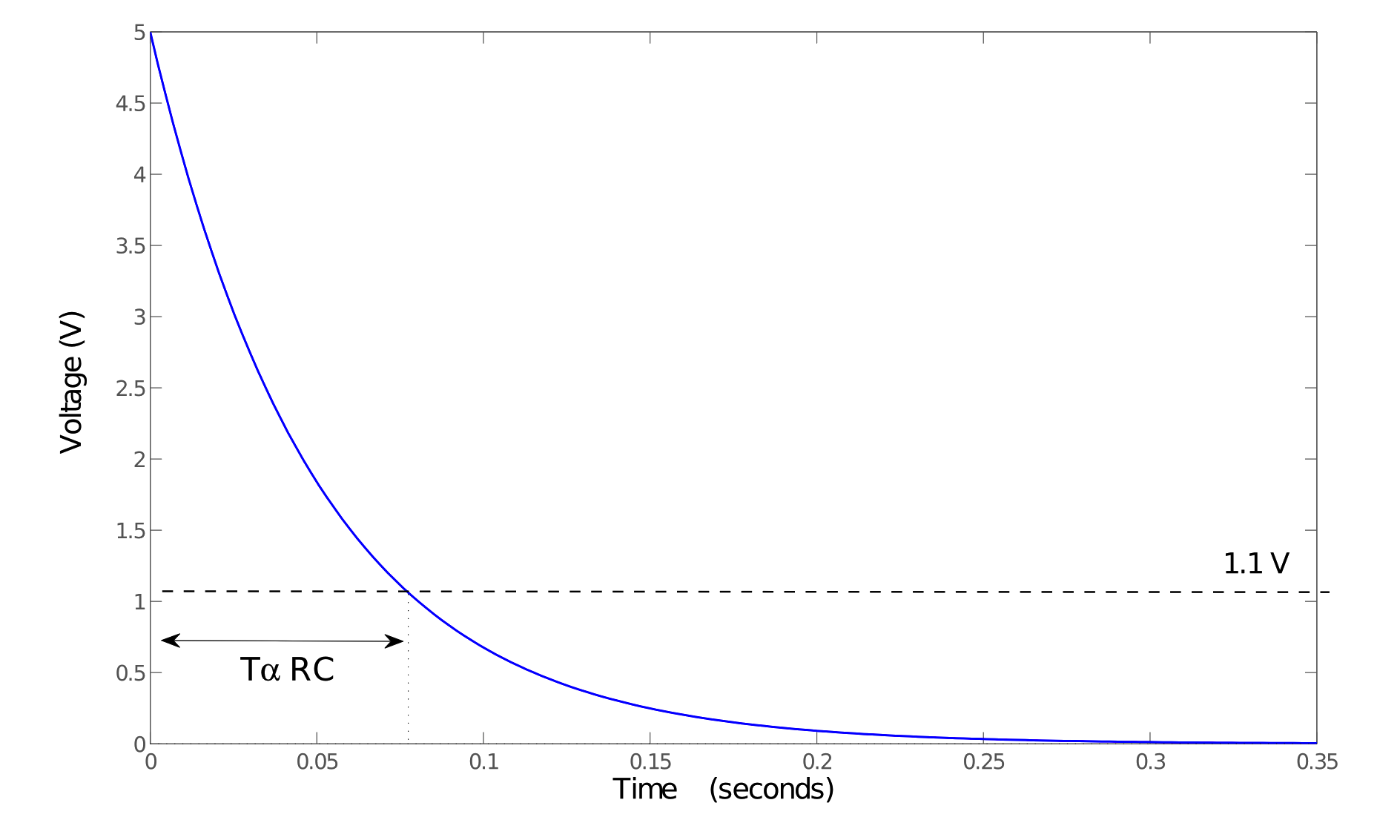
I found that I had to incrase the resistance of the RC circuit but otherwise the board worked perfectly to measure small capacitances.
I calibrated the board using a series of known capacitances from 1pF to 1000pF.
I was then able to generate a plot of the capacitance of the discrete capacitor vs. the number of vertical units:
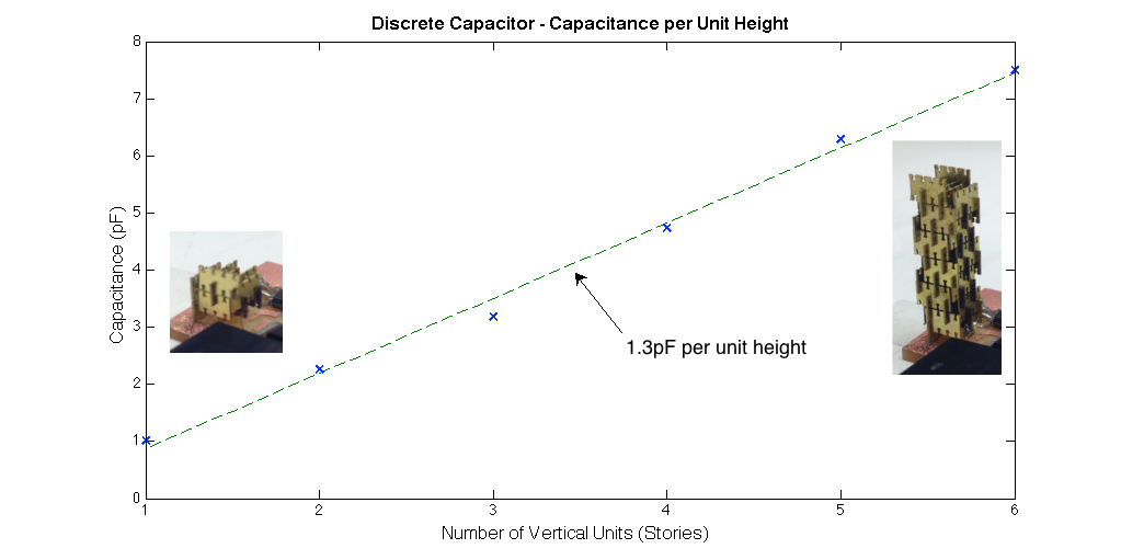
This data is very much inline with my original back-of-the-envelope estimates. That is to say, I estimated 35 conductive parts would make capacitances on the order of 3pF and found that they actually made about 7pF of capacitance.
I wasn't content with just getting a value of the capacitance. I wanted to see phase lag and lead. This requires doing either a frequency domain analysis or a time-domain analysis. I chose to do a time domain analysis using a signal generator and oscilloscope.
I knew I wanted to minimized the impedances (both resistance and reactance) of the wires I'd use to connect the devices to the scope and signal generator. I figured BNC connectors would be a good way to do this. I was wrong.
I realized that there was a ton of capacitive load while using the BNC connectors. When I did measurements with known capacitors, anything below a few microfarads was washed out by the capacitance of the sensing system.
I did some reading and it turns out that oscilloscopes generally have large capacitances in parallel with the input ports. This is designed to reduce noise caused by restistances (sqrt(4kTR)) but also causes problems when you want to measure very small capacitances at high frequencies.
The solution then, was to use o-scope probes. These are specifically designed to reduce the effect of this capacitive loading.
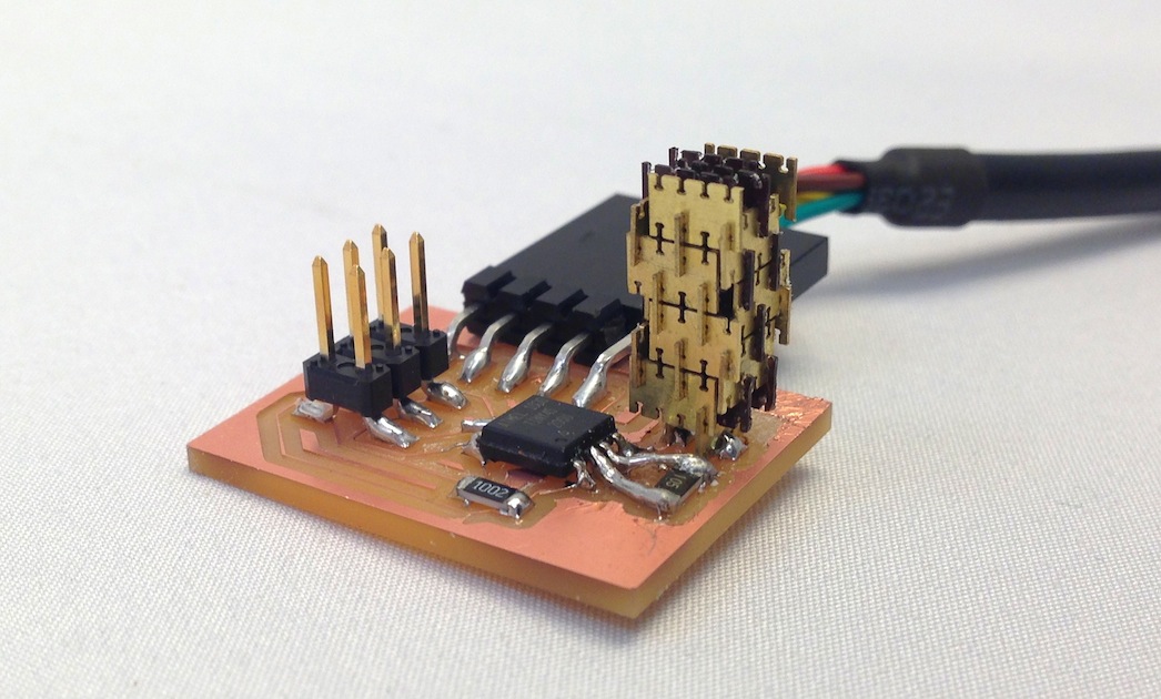
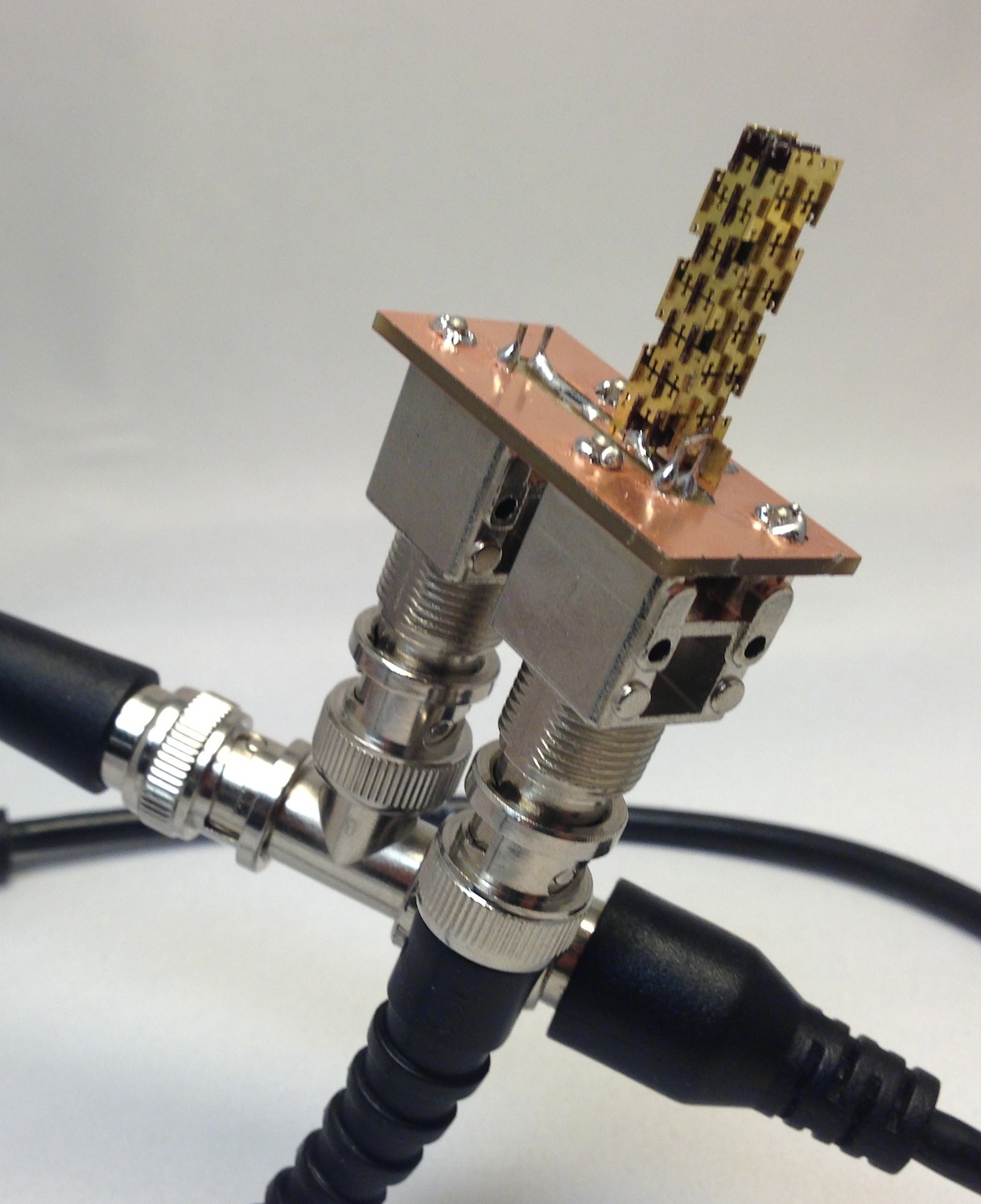
Having discovered this, I made some probe-boards to house the RC/RL components and ensure good connections to the probe tips.
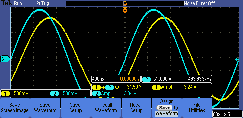
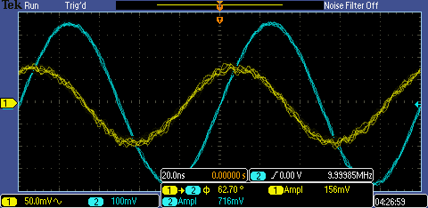
Here is discrete capacitor demonstrating phase lag with respect to the input and the discrete inductor is demonstratin phase lead.
 |
 |
 |
 |
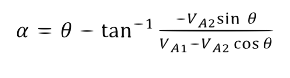
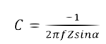
Capacitance and inductance can be calculated from the amplitude of the input and output waveform as well as the phase shift at a given frequency using the following equations. Here, Va1 in the sinusoidal input, Va2 is the voltage across the capacitor or inductor, and theta is the phase shift.
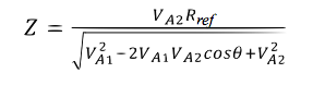
Then, for a capacitor,
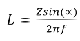
and for an inductor,
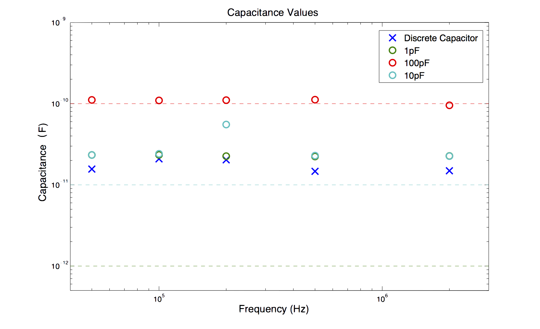
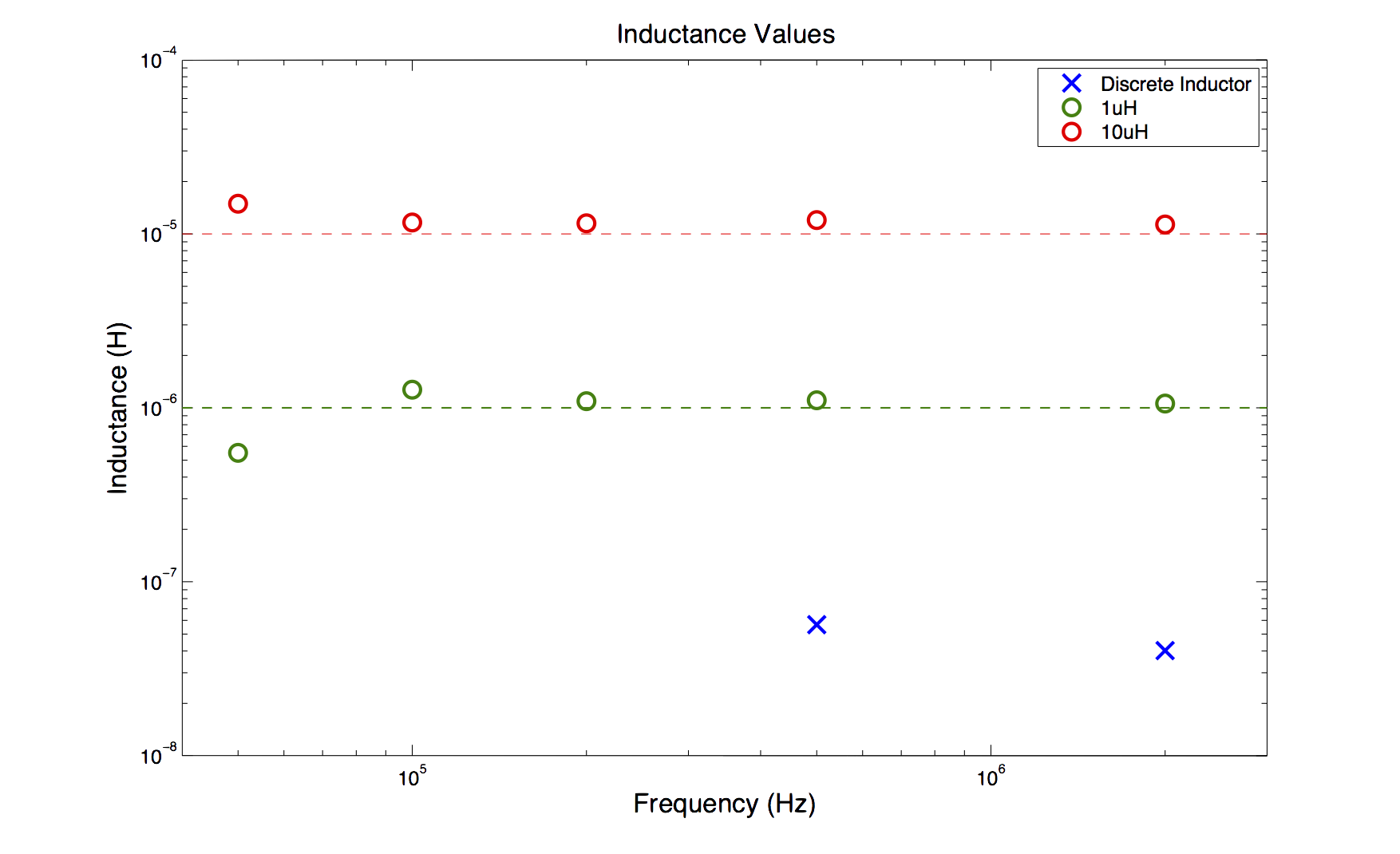
I made these calculations at a range of frequencies from 50kHz to 10MHz. The results are shown below:
The time-domain analysis was not nearly as sensitive as the step response test was for small capacitances. Its inability to measure below 20pF leads me to believe that this is a capactive loading issue resulting from the the measurement setup (e.g. probes).
The time-domain analysis did much better with the inductors. At low frequencies the discrete inductor attenuated the entire signal but let some signal through at higher frequencies.
I've shown here that it is possible to discretely assemble functional passive circuit components. Furthermore, from the same set of parts it is possible to "program" phase-lag or phase-lead into the structure depending on the placement of the parts.
As I discussed in the the back-of-the-envelope section, there are signifcant benefits that come from scaling down the part size since capacitance scales with the characteristic length but volume scales with the cube of the characteristic length.
The inductor geometry presented here was far from ideal. It is possible that introducing a new part-type could solve the problem of spatial-density for the inductor.