Micro-controller Programming |
|||
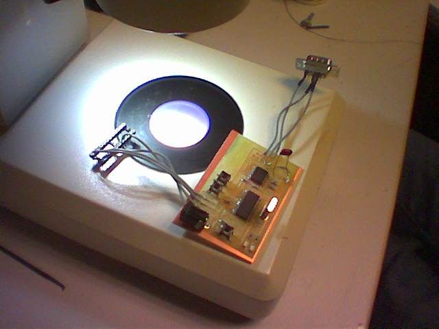
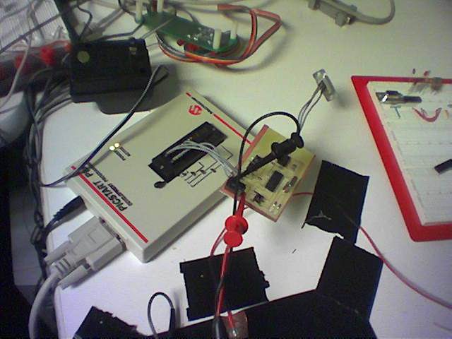
| PIC Micro-Controller Burning (with addendum from Ben Dalton): 1. Get all your components mounted onto your board. Make sure you know which PIC controller you are using. check all paths with a multimeter in beep mode for good connections. Check that all ground lines are connected and all power lines as well, and check that your ground and power lines are not shorted while you're at it. 2. Connect your programming ports to the programming bed/stand/dip/adapter thingy:
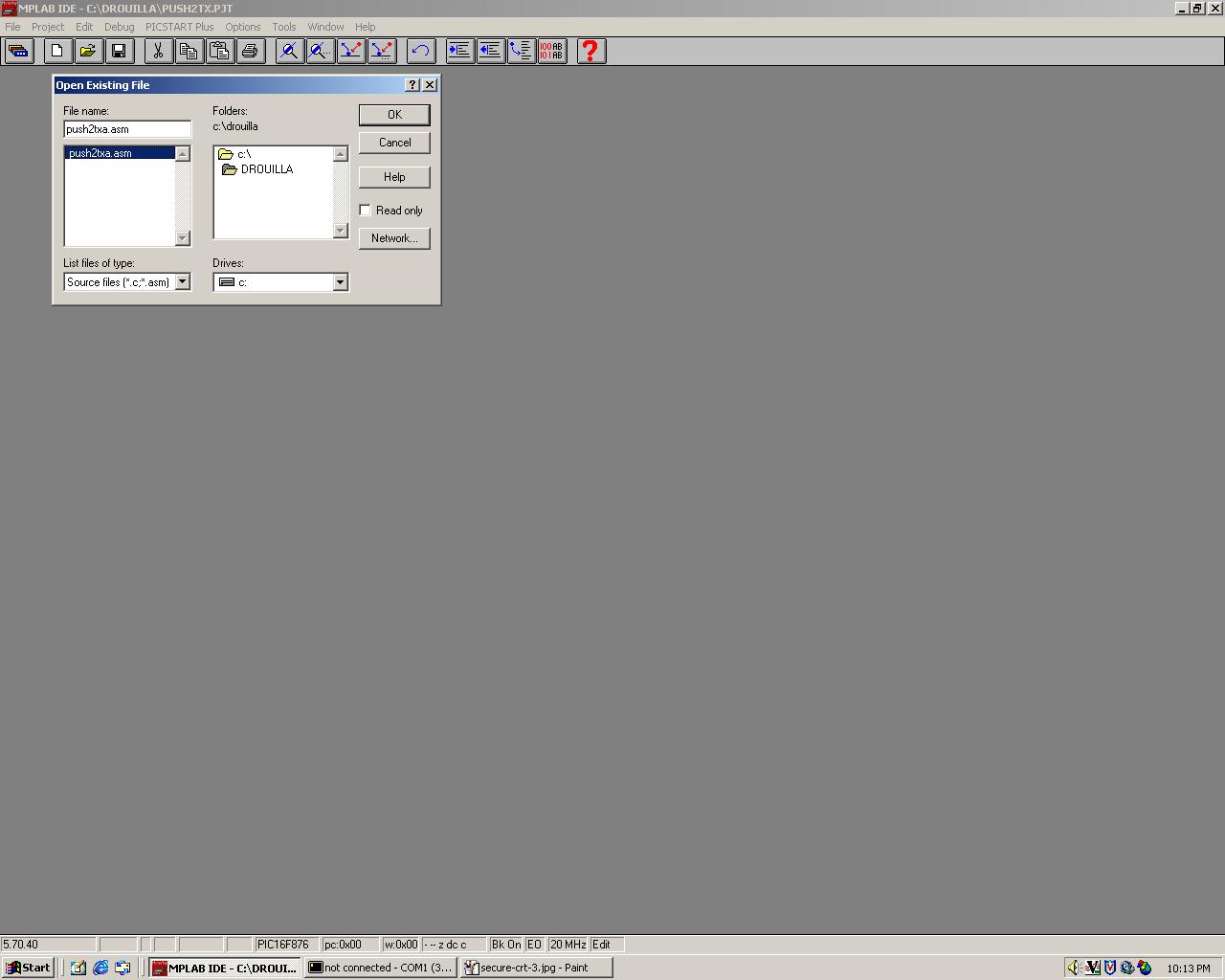
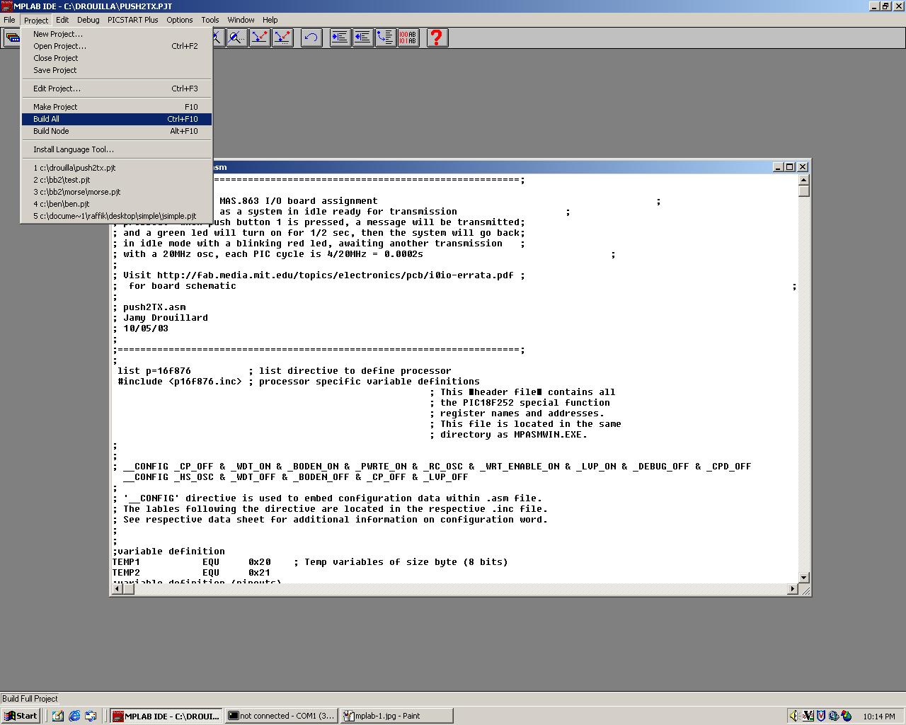
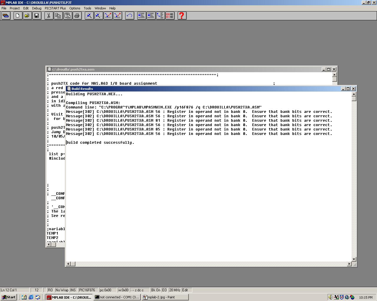
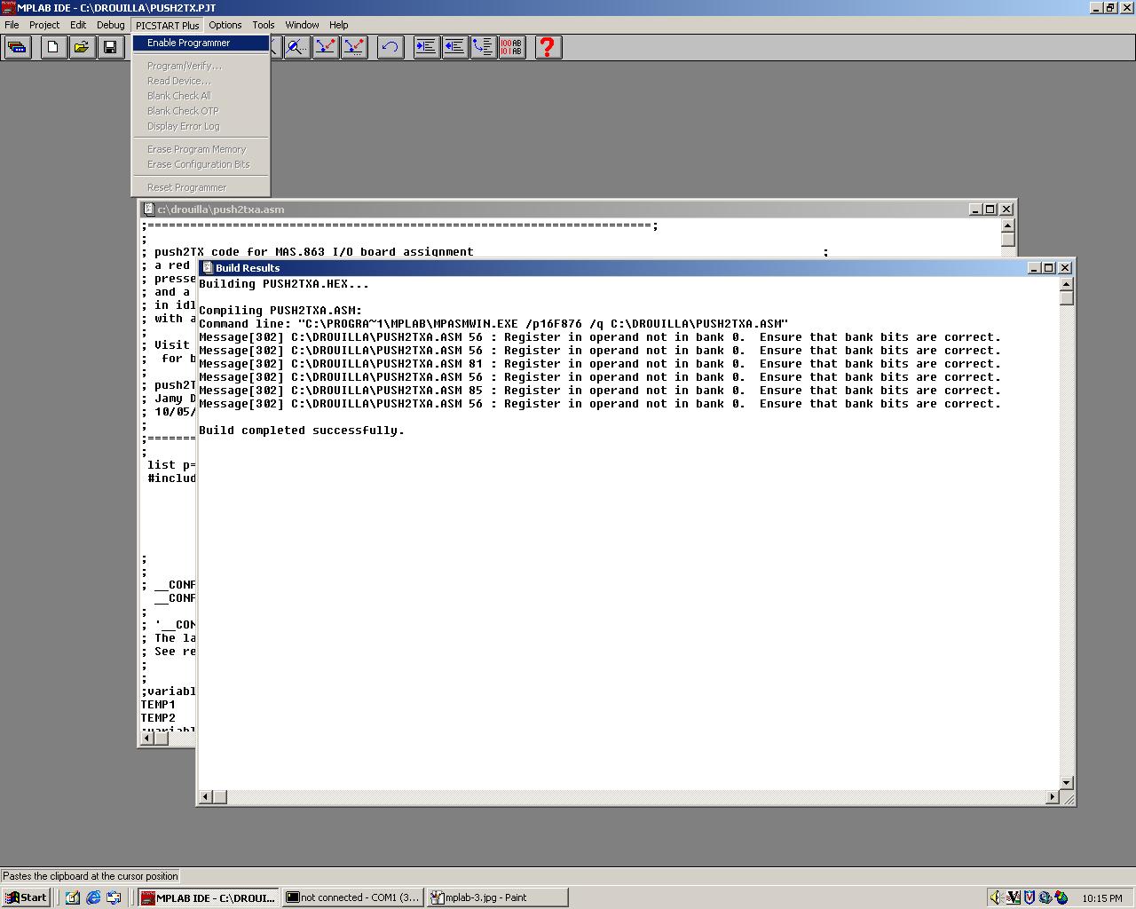
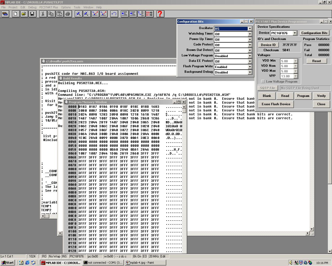
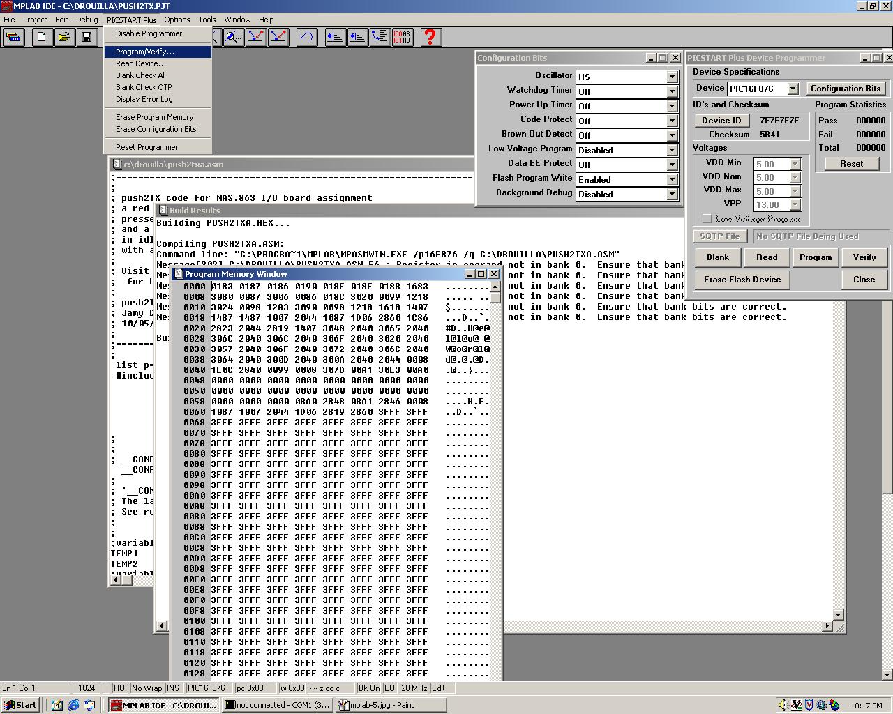
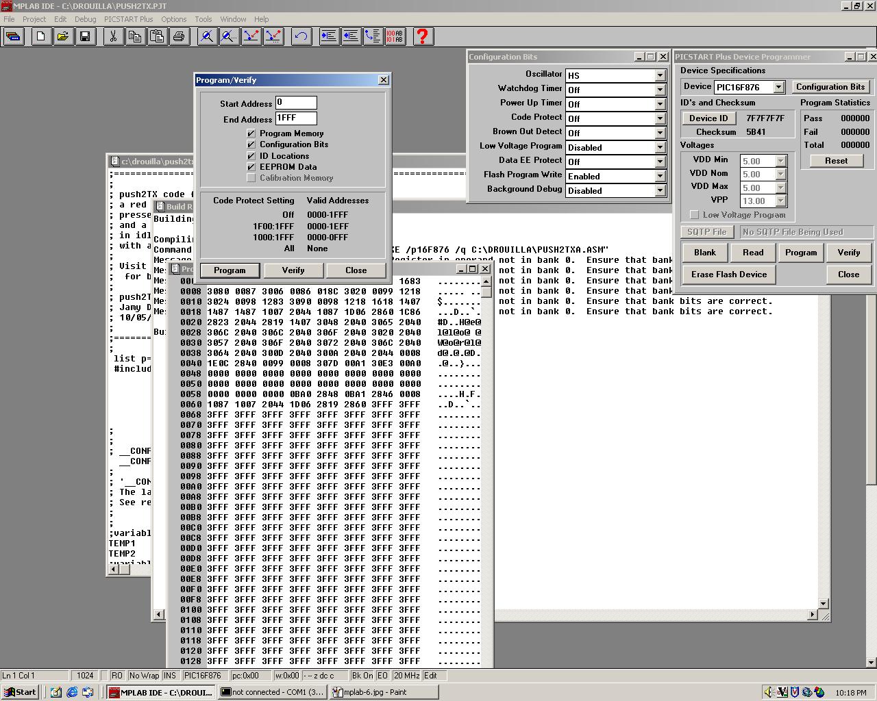
3. Connect power and ground on your board to the power supply, (and supply it with +5V DC). If you set the 5V, on the power supply, turn it off with the button, then connect your board, then turn it on, you can check your current draw (on the power supply) is in the ~0.02A range. If it jumps up, turn it off fast and check for shorts on your board. 4. Place your adapter into the PICSTART programmer, with pin 1 on the top left, right next to the lockdown lever. 5. On the computer, open up MPLAB (the old version, cause I don't think the new version works), and open <your-code>.asm (assuming it's on the computer already, if not download/transfer it into a folder with your username (or whatever) as label). Load <your-code>.asm as a 'node' after selecting New Project" from the file menu. 6. Make the appropriate changes to with the header: PIC16F876 or PIC16F876a 7. On the top menu bar, open PROJECT --> BUILD ALL, and let it compile. Hopefully you'll only get warnings/messages, and no errors. If you get some errors, then you gotta debugg and fix them (double click an error to jump to it in your assembler code), and reapeat step 7. If not, then you can proceed. It should automatically create a project for you, but if it doesn't, then create NEW PROJECT, then add <your-code>.asm through ADD FILE, then compile it. 8. From there, go to PICSTART PLUS --> ENABLE PROGRAMMER. A series of windows will open up, including a PROGRAM MEMORY WINDOW, which tells you how much of your flash memory is being used up by your code. Sections of this file with 3FFF are essentially blank. Record the first line (on the left) where the rows of 3FFF begin, for example 0068 is the first row of full 3FFF, then I'll record/remember 6F, 007* will be 7F, etc... Not crucial, but will save burning time. The 'a' variety chips have to be programmed in 8 word blocks (so your end address must be a multiple of 8 - in hex this is any number ending in an 'f'). 9. Go to PICSTART PLUS --> PROGRAM/VERIFY, and a new window will pop up. Type the END ADRESS as the one you just recorded, (i.e. 6F if line 006* is where the 3FFF series began), and then hit PROGRAM. If you don't know the end address, or don't care about time, then just program it with the default values (1FFF). If you have an 'a' variety chip, you must click "Erase Flash Memory" before every program for it to work. 10. If successful, then you will see success on the window. You may safely remove your PIC adapter, power it with the power supply, and try running it to see if it does what you told it to do. If not a success, then one of many things might be wrong (power, serial port connected, SecureCRT open and active, bad wiring on the board and/or adapter, etc...) I don't know enough yet to answer that here, but I'll gladly sit and figure it out with you when Raffi or Ben B. aren't around. If your chip does not program. Check your connections with a multimeter. Make sure you have added the capacitor between the max chip and ground. Check you have powered up your board (as the other components draw power away from the chip during programming). Check you have 5V on the Vdd port of your PIC with the oscilloscope. Check you have set the correct chip number. Try pressing "Erase Flash Memory" and then "Blank", if you have a connection with you chip, it will now be blank. If your program doesn't seem to work as expected. Check your clock/crystal with the oscilloscope, you should see a sort of square wave (not really, but the oscilloscope should measure a somewhat steady 19.5-20.5MHz frequency). If it isn't there, you may need the tracks from the crystal to the chip to be thicker, and shorter for it to "ring up" correctly.
A message from BB2 about connecting serial ports and stuff:
|
|||