final assignment [Final] :: describe your final assignment :: for the final assignment, we would like to make a working prototype of the macro-pick and place machine using the various methodologies that we've learned during the semester below is a diagramatic version of what the machine will look like - NOT ACTUAL DESIGN the final design of the machine will be determine later. **for a brief history of the project, please click here
:: components ::
 the machine is made up of 5 parts:
1. : the tower - that controls the Z-direction
2. : the arm - that controls the Y-direction
3. : the base - that controls the X-direction
4. : the gripper - that holds and releases an object
5. : the hopper - that contains the object
the machine is made up of 5 parts:
1. : the tower - that controls the Z-direction
2. : the arm - that controls the Y-direction
3. : the base - that controls the X-direction
4. : the gripper - that holds and releases an object
5. : the hopper - that contains the object
:: actions ::
 the movement of this machine consists of:
1. : the arm locates the object in the hopper
2. : the base moves to a particular location
3. : the arm moves up the tower in the z-direction
4. : the arm moves in the y-direction to locate the object
5. : the gripper then adjust to the rotational direction of the object then releases
the movement of this machine consists of:
1. : the arm locates the object in the hopper
2. : the base moves to a particular location
3. : the arm moves up the tower in the z-direction
4. : the arm moves in the y-direction to locate the object
5. : the gripper then adjust to the rotational direction of the object then releases
:: things we will need :: we will need to design/make/buy the following: :: HARDWARE :: [if possible, all parts will be fabricated locally] BASE: Chassis (laser cut/water jet cut pieces) Wheels Servo motor/DC motor? Gears TOWER: stepper motor attach to screw shaft for Z movement guiding tubes – for precision control and smooth movement ARM: stepper motor to control arm’s movement guiding tubes – for precision control and smooth movement GRIPPER: stepper motor for actuator to holds and releases a joint ATMega32 microcontroller Headers for connecting motors / programming interface / PC :: SERIAL INTERFACE :: AC plug 9V AC/DC converter Actuator guides (metal rods) Arms screws, 3D printed or injection molded parts Serial connector / Serial cable for PC communication Parallel cable for programming LED's RF link??? :: SOFTWARE :: Microcontroller ASM or C code for controlling the actuators Python script for communication with the PC
:: SCHEDULE :: 11/29 - electronics/parts 12/06 - assembly/programming 12/13 - final project presentation
:: PCB ::
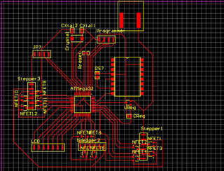
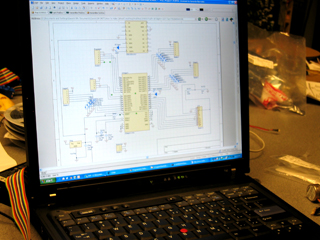
 this is our layout for the PCB that we will be using to control the machine. the micro controller that we will be using is the Atmel ATMega32
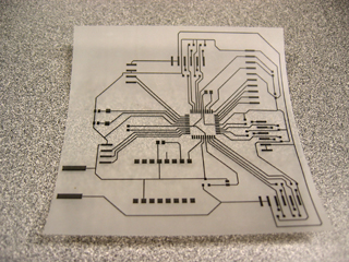
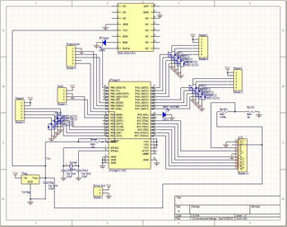
 after layout, we printed the schematic out for etching
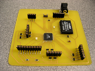 this is our board after etching and stuffing it with components
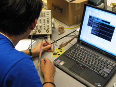
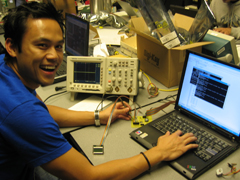 then we had to program it....and it works!!!!!

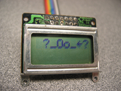 DAMN LCD!!!
code issues:
- PULSE VALUE
: in order for us to generate enough torque to even move the motors
we had to alternate between various pulse values for each of the motors
: LCD - character output - timing issues within the code
DAMN LCD!!!
code issues:
- PULSE VALUE
: in order for us to generate enough torque to even move the motors
we had to alternate between various pulse values for each of the motors
: LCD - character output - timing issues within the code
:: MECHANICAL PROCESS ::
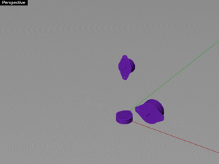
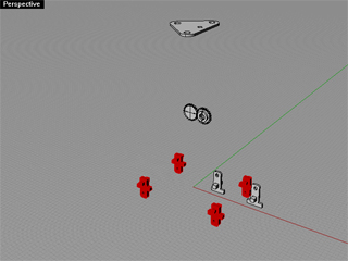 these images show the parts that we will fabricate (from left to right) using the water jet cutter, the 3D printer (stratasys), and laser cutter.
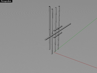
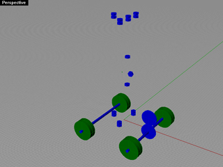
 these images show the items that we either will buy or have laying around. (from left to right) they are the rods (screw shafts), nuts and screws, and 3 different types of motors
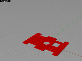
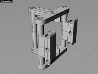
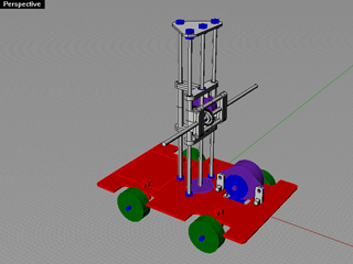 this is the complete computer model of the machine done in Rhino
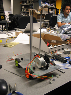
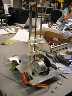
progress images...
this is the complete computer model of the machine done in Rhino
progress images...
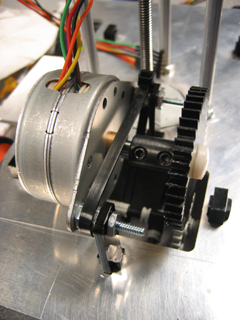
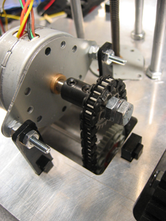 mechanical issues:
- gears and their rotations
: if less torque is required, the circumference of the head gears
(center on the motor) need to be smaller than the linking gears
: if more speed is desired, then the opposite configuration would
take place
- getting the actuations to work with minimal torque
- slippage in movements
- tolerances
- gripper : uh..the problem is...we haven't design one!
- load : the mechanics had to work flawlessly in order for the motor
generate enough torque to drive the load of the machine
mechanical issues:
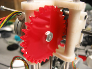
- gears and their rotations
: if less torque is required, the circumference of the head gears
(center on the motor) need to be smaller than the linking gears
: if more speed is desired, then the opposite configuration would
take place
- getting the actuations to work with minimal torque
- slippage in movements
- tolerances
- gripper : uh..the problem is...we haven't design one!
- load : the mechanics had to work flawlessly in order for the motor
generate enough torque to drive the load of the machine
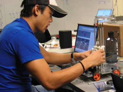
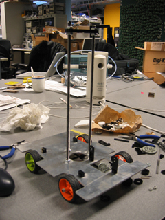
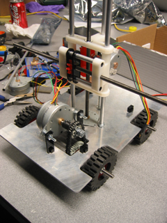
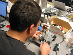
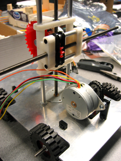
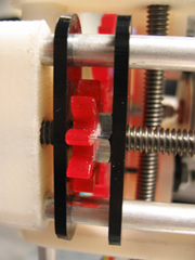
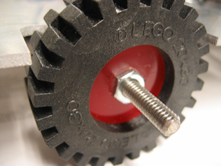
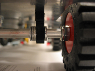
:: ASSEMBLY ::
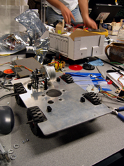
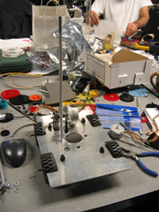
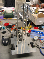
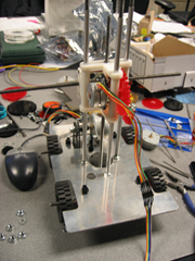
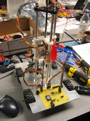
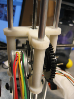
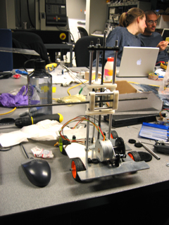
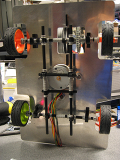
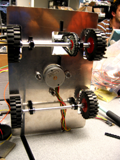
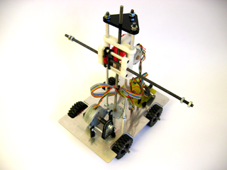
:: PROGRESS ::


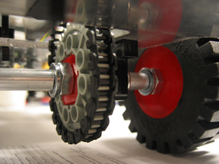
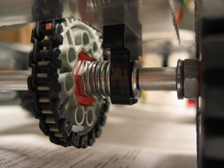
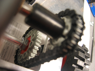
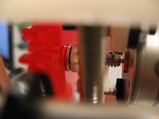
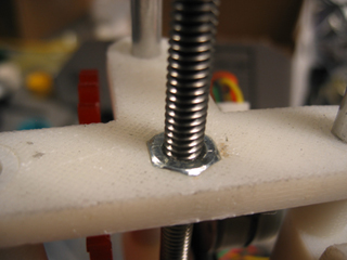
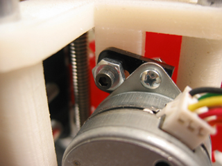
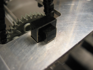
:: MECHANICAL DETAILS :: : we fabricated as much as we could with the exception with some of the parts : with the tires, we used the rubber cover from lego parts then we cut the wheels out of 1/4" acrylic, sandwich 3 layers inside the rubber cover with one layer indented for the nut (controls the rotation of the wheels) to be set in - we then tight another nut on the other side and hold the wheels together with friction : the tower (z-axis) works with a rod connected with a set screw at the center of the motor - as the motor turns, a screw is set inside the mid-section (arm holder) so as the rod turns it moves the entire center piece in the z-direction : the same mechanical action for the tower is then translated to the movement of the arm : for the shaft of the wheels, we cover the rod that spans from tire to tire with an aluminum tube in order to keep the equal separation - especially the shaf that drives the back wheels since we needed to hold the gear in place in order for it to make contact with the motor above - we used washers
Copyright © 2004 - Massachusetts Institute of Technology - Han Hoang and Gerardo Barroeta