MAS.863 - Fall 2005 - Samuel Lipoff
Update Update! - Quicktime Files
14 November 2005 - Scanning and Not So Rapid Prototyping
I see why "rapid prototyping" is someimtes called "not so rapid prototyping" although it sure beats hammering on marble with a chisel. :) Actually the most frustrating thing was closing the holes on the objects that I scanned using the laser range finder! The Z-corp machine can at least run unattended
Interestingly, I happened to attend a talk at Harvard this past week by Hanspeter Pfister at MERL on an alternative method of scanning objects. It lacks the resolutions and realism of laser range finding, but runs unattended and allows scanning of even objects with fine features, such as feathers or fur. Here's their paper, which incldues collaboration with MIT: Image-based 3D photography using opacity hulls
I scannned my classic, vintage, workhorse, 9-year old Motorola StarTac cell phone. I didn't scan this ubitiquous object simply because it's been my companion since 1996, but for a real world application of laser range finding and rapid prototyping. My father is a cellular telephone engineer, and has been working on a new design of a kind of satelllite phone that requires an additional 20% internal volume to accomodate the satellite antenna and electronics. This means approximately an extra 4% in each linear dimension. To see how increasing the phone size at that scale feels, what could be better than scanning an existing cell phone, and then printing copies at different sizes to test their usability?
7 November 2005 - Oscilloscope
I'm working on the oscilloscope . . . and now realize that most of the functionality will have to be expressed in microcode, because short of additional features (e.g. multiple inputs for X-Y mode, different triggers, etc.) we've already implemented a volt meter. I'm learning this assembly language, but hope to report back with a working oscilloscope mode soon!
31 October 2005 - PCB Fabrication and "Stuffing" Take 2
This time around, no problem. :)
I made both the the original hello-world PCB, and the hello1, and hello2, and the new and improved combination serial I/O and LED indicator light boards. I've learned several things about milling PCBs:
- It is very important to tape the board down very solidly to the Modela bed. This is more to prevent the board from being warped, rather than simply to prevent it from moving. I'm not alltogether happy with the concept of taping boards down (as opposed to some other mount) but unless I invent something better, I shouldn't complain :) If a board is too warped, it's probably better to discard it and use another.
- If you countour and raster, using cam.py and then change the X-Y offset, the screen image still shows a countoured and rastered file, but it won't actually raster the physical output. You must first set the offset and then contour and raster.
- Setting the cut a little deeper than the default is often a good idea and can help to correct problems caused by the board warping.
- When it doubt, use a new tool. I was getting strange artifacts, but then switched to a new tool and they disappeared.
Knowing these tips in advance would have saved a lot of time. :)
As for soldering . . . well I've soldered a lot in the past, although never components quite so small (I'm used to thru-hole components). But it wasn't much trouble to solder these little componets down. Making cables took more time, and it feels like there should be a better way, but both cabled worked, and weren't too bad, especially with the nice vices and extra "hands."
24 October 2005 - PCB Fabrication and "Stuffing"
I tried to fabricate the PC board several times using the Modela milling machine. I really like the Modela a lot, but due to some problem that was difficult to identify the cuts were so uneven that I was unable to get a working PC board. At first I thought it was the stock I was using (i.e. the individual board was warped) but similar problems occured with several different boards, and I think it may be the bed of the machine itself. I tried playing with the cutting settings on the Modela, thinking that there might be an optimal setting that would result in a working board, but I was unable to find that setting, I moved ±2.5% and ±5% from the suggested cutting depth, but on all five boards was unable to get a uniform cut that would work. I also tried varying the position of the board on the platen, thinking that it might have an effect. Maybe I should have tried to control variables better, but I also had to change tips during the experiment!
I will try again this week and make sure that I can get a working board, and program the controller. I'm very excited to implement working RS-232!17 October 2005 - Final Project Proposal
To make the Bookscanner, I will need the following components:
- A 90 degree V shaped stand to hold the edges of each book.
- Screw threads on each side of the stand to move in up and down.
- Quick clamps to hold the back of each book.
- An arm with a vacuum clamp to turn pages.
- Two sheets of glass to hold down each page and complete the turning, on a bracket that slides up and down.
- Sensors to tell when a page has been turned, logic to backup if the page did not turn properly, and to change the height of the stand to keep the planes in focus.
- Optics, or, more likely, a sliding bracket. to move the camera to each side of the book.
- Polarizing filters over the camera lens and the flash gun. Light meters on a feedback loop to the flash.
- Plastic shields to prevent reflection from the flash.
The largest challenge is the manipulation of paper, and turning pages. I've been playing with vacuum lifters and playing with moving pages back and forth.
10 October 2005 - Supersonic Waterjet
For the superosonic waterjet I elected to make a set of 1/16" aluminium tiles in an unusual pattern, namely a set of three "fish shapes" that could be rotated around 30 degree incremenets to make an asymmetric tiling of the plane. Individually the three pieces look like this:
\
They can be rotated in unusual ways so make an asymmetric plane tiling. I saw something similar once as a child's toy but didn't remember the name of it, and couldn't find it on-line, (how do you search for "press-fit fish"? So I remade the angles.
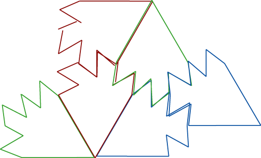
l used Adobe Illustrator for the design, and then imported the DXF file into Omax. Omax actually seems to be a very nice program, but I still feel more comfortable using Illustrator, and the latter has more general 2D drawing features. I did find I had to be very careful when importing the DXF to close gaps in Omax. Because the pieces I made were so small, I tried to place small tabs on their edges to prevent them from falling in the bath. This was not successful, and also left scarring on the the pieces, so I made them on the block instead. I made several versions, using different cut quality to see which would fit together the best. It turns out that using a design that had the angles deliberately slightly off, with a relatively poor quality of the Waterjet cut (Q3) produced pieces that would fit together extremely snuggly. I liked the idea of rough pieces fitting together like a jigsaw puzzle! John also showed me a trick to make sure that the tool path is always on the correct side of my pieces.
I also tried to make one other pieces, a hangar that would fit over my door, since my closet door is too narrow for the commercially available versions, and the door to my room is to wide! I made the following drawing in Illustrator, but the DXF did not import correctly. I remade the piece in Omax, and cut it, intendning to bend the final shape, but I did not take into account the radius of the bender, nor the flexibility of the stock that I used. I'll have to try this one again.
1
October 2005 - Press Fit Assembly
The assignment this week was to make a "kit" that comprises
a relatively small number of parts out of which you can put together
more complex (particularly 3D) structures by joining individual parts
via-press fit assembly --using friction and compression/expansion of
the material itself to hold the structure together, rather than external
adhesives, fastners, magenets, etc.
The laser cutter really is a neat tool, and after seeing the demonstrations of what it can do, I had several ideas for things I wanted to make with it. Some completely 2D ideas first sprang to mind, like making a set of tangrams, and a 2D jigsaw puzzle. But then I started thinking in 3D and, being a chemist, I knew I wanted to make molecular models. The other idea I had was to set some general constraints and parameters, and let a computer program generate a set of random press-fit parts. If you also give the computer a set of larger structures to build, and let it generate random parts, try them in different orientations, and refine those parts based on some fit criteria, one could generate a "kit" with an evolutionary alogirthm. But this sounded like too much work for a weekly assignment, more like a PhD thesis! :) But molecular models are very interesting, so I eagerly returned to them.
I made a few sketches of possible molecular model ideas, and then went to look to see what kinds of models have been made before.
Most molecular model kits in common use today look more or less like this, and are used mostly for organic chemistry. Sometimes extensions to these kits that have balls with holes drilled for square planar, octahedral, and trigonal bipyramidal complexes that are found in inorganic compounds, can also be bought. Sometimes kits for larger biological molecules can also be bought, where the parts are considerably smaller, such as in this example. These kits work better for organic chemistry where most atoms are tetrahedral or trigonal planar carbon, and bonds lengths vary relatively little. Biological molecules can also be built with such kits, although very large biological molecules become tedious to build when one has to show each non-hydrogen atom explicitly. These kits are good at showing structure and rotation (and hindered rotation) but are not sufficient for inorganic chemistry or solid state chemistry, where bond lengths are more unusual coordination are essential. There are some specifically inorganic model kits available, such as this one, and have many different bond lengths and atom centers with unusual coordinations. The "zome" model system, pictured here, can also be used to model inorganic and biological systems. The zome node consists of a truncated polyhedron with 12 pentagonal, 20 triangular, and 30 rectangular holes that produce 5, 3, and 2 fold axes respectively.
But when inorganic chemists draw models of complex solid-state structrues they typically do not use the same "ball and stick" approach where atoms are represented by balls and bonds by sticks, or atoms by crossings of sticks, but rather by drawing polyhedra, such as tetrahedra and octahedra, and sometimes representing additional atoms as balls that fit into pockets created by those polyhedra as in this figure of a perovskite structure. Such diagrams can be quite complicated, as in this example. I'd never seen such models available in a kit, although I did know that van't Hoff, who was said to have made the first 3D physical molecular models, used something rather similar, namely these.
I also looked through several books, and articles about molecular models in the Journal of Chemical Education to look at the prior art. Most involved three-dimensional models, but there are several exams of making models from planar components.
So I ended up fabricating three different kinds of molecular models:
- Press fit molecular models made out of interlocking cardboard cirlces with grooves cut in them for assembly. These are analogous to the standard molecular model kits primarily used for organic chemistry except that they are made entirely out of planar forms and I made octahedral, square planar, trigonal planar, and trigonal bypyramidal forms.
- Experimenting with press-fit fold-up tetrahedra and octahedra by sliding supports into the corrugations in cardboard.
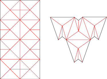
- Molecular origami by scoring paper with the laser cutter so it easily folds into polyhedral forms which can then be placed together, even by a type of press-fit assembly.
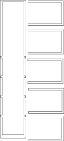
The set of molecular models I made entirely by press fit assembly look like this:
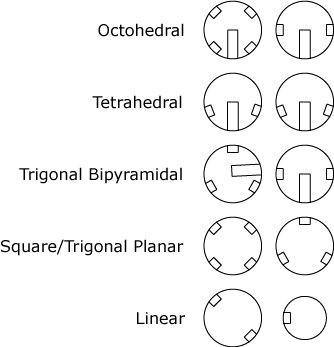
For octohedral, tetrahedral, and trigonal bipyramidal coordination the two dics slide into each other, and the small notches can be used to describe valence. For the planar coordinations, the dics can be used by themselves.
The second type use the coorugations of the cardboard to "press-fit" assemble the tertrahedra and octohedra.
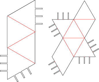
The origami moles of octohedra and tetrahedra looked like this, where the red lines indicate score lines, rather than cut lines.
To cut cardboard I used 60% power, 15% speed, and 250 ppi. To score cardboard I used 55% power, 60% speed, and 250 ppi. To cut paper I used 15% power, 60% speed, and 1000 ppi. To score paper I used 7% power, 80% speed, and 1000 ppi. It really helps to hold down the edges of the paper (both right and bottom, as the top and left are held in place by the frame) while cutting so that it doesn't flap up in the strong gases. I also learned that it is important to make sure the cardboard is very flat on the bed (ideally it should be pressed overnight)
26
September 2005 - Final Project Preliminary Animation
I animated the Page Turner & Photographic Copy Stand for Books
that I've briefly described in the previous entry. I did spend
some time learning Blender, but I used SketchUp for this drawing and
animation. I feel that the animation is still fairly crude, and it's
missing some of the essential components, but I think it will be sucessful
in communicating the basic idea. I've learned a lot by trying to animate
this device, and see it's worth trying to improve the 3D model. In particular,
I've learned that it really helps to create each component individually,
and then try to slip them into a composite model. Click on the image
below for the MPEG file.
20
September 2005 - Final Project Early Concepts
I
have several early ideas for the final project, all related to manipulating
paper in one for or another. Although I'll settle on one for the CAD/Rendering/Animation
for next Monday, I thought it might be a good idea to list a few here,
with some short explication of each:
- Page
Turner & Photographic Copy Stand for Books
The concept is to have an integrated device that incorporates bracket to place a book at a 90 degree angle, a page turning mechanism, a brace for a digital camera to swing to address either side of the brace, and a connection between the camera mount and the brace to allow rapid scanning of bound matter. Additional software and sensors to aid in the process could be added. Manu suggested that a scaled down version of the device (i.e. a page-turner) could be made as a weekly assignment. The full version with all the bells and whistles would probably be a term project. (The links here are not to exactly what I'd want to bulid, but just to give an idea of the prior art!) - Filing
Robot
A filing robot would be a device that manipulates individual sheets of paper, possibly with air knives, possibly with vacuum cups, Vibrating joggers or other implements to sort, move, file and generally manipulate individual sheets of paper. - Origami
Robot
An origami robot is a machine that can take a sheet of paper and make various folds, unfolds, creases, pulls, and other manipulations that occur in the general practice of origami. Such a machine would allow one to make various origami shapes by programming the desired folds. Take a look at just such a device. - Paper
Cutting Robot
Consider the origami robot, but one that can cut paper as well as make folds and creases to make popup greeting cards like these or these. The "phase space" of folds and creases may not be as large as the general origami robot, so this may be easier in some sense.
I will also list a few other things that I'm interesting in making---maybe they will become weekly assignments, or maybe they will just be listed here to remind me that I had some idea at one point!
- Vertical holder for Panasonic R3 notebook computer with cutouts for power, video, and USB (with integrated, powered USB hub).
- Reprise of various historical and modern molecular model sets for chemistry.
- Set of crystal unit cells for all possible space groups (similar to set that Professor B.J. Wuensch has in his office).
- Foam cutouts to tightly hold various office supplies for travel.
- Copy a key.
- A penguin statue.
20
September 2005 - Introductory Bio
My name
is Sam Lipoff, and I'm a first year PhD student at MIT studying chemistry
(i.e. Course 5). I'm a physical chemist (or chemical physicist depending
on your preference) primarily interested in making ultra-cold molecules,
studying them spectroscopically, and (hopefully) doing ultra-cold chemistry
with them. I've always been a spectroscopist, but in previous research
I worked on single molecule spectroscopy for imaging biological molecules,
and even earlier, integrated optics for ultra-sensitive fluorescence
detection. I did some "fabrication" then, in both traditional
"hard" lithography (photoresist, various etchings) and "soft"
lithography (in PDMS) for microfluidic channels. Of course, chemists
do "fabrication" (in a manner of speaking) at the nano-scale
or below all the time!
I was an undergrad at that other school down the street in Cambridge, where I was a joint concentrator in "Chemistry and Physics" and "History and Science" with a particular focus on Chinese history. I also spent a year in the "other" Cambridge, doing a master's degree in history of science, with a focus on history of science in East Asia, and have spent considerable time in China, Japan and (South) Korea. I like to make things too!