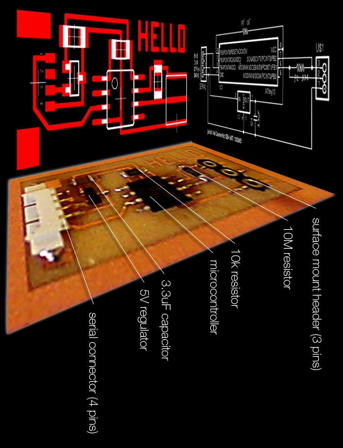
The fifth assignment was to make a DVM/resistance,capacitance,inductance meter/oscilloscope/logic analyzer/... that can be used to debug other circuits.
Objective: make a circuit board that can be used as a voltmeter
Materials: soldering iron, solder, copper plate, end mill, microcontroller, 2 resistors, capacitor, regulator, Molex serial connector, surface mount header, potentiometer
Procedure 1: Using the Eagle application, prepare the .cmp file for routing
- Open a terminal
- Type “Eagle”
- Go to File >> Open >> Schematic
- Browse to Desktop >> Fabdownloads >> hello.sch
- Look at and check both the schematic view and the board view
- From the board view, go to File >> CAM Processor
- Designate file name, i.e. “matt_hello3.cmp”
- Browse to the desktop to save location
- Deselect all the layers and click “Process Job”
- Designate output device: GERBER_RS274X
- Gradually select layers as the CAM Processor needs them (it will tell you!)
- Take your new .cmp file to the router or vinyl cutter
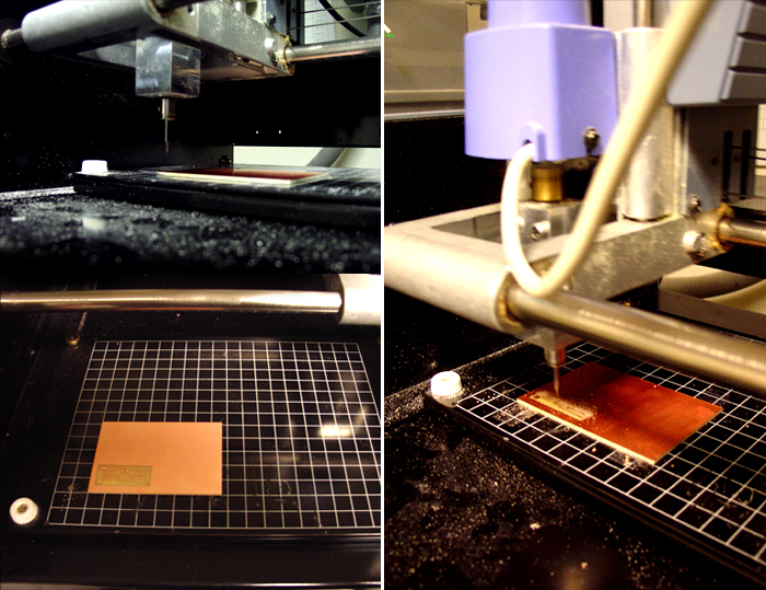
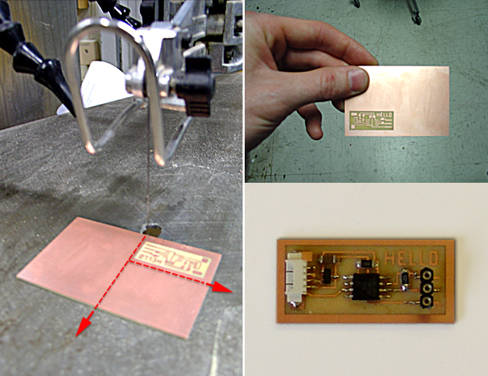
Procedure 2: Using the Modella CNC router, remove the copper from the copper plate that is not part of the circuit.
- Open a terminal and type “cam”
- Input your .cmp file, i.e. “matt_hello3.cmp”
- Tape the copper plate to the bed of the router using double-sided tape, making sure that the tape overhangs for easy removal later on.
- Tape the plate down, 2 squares up and 2 squares over.
- Click “Auto Scale” to see the circuit at a larger scale.
- First press “contour”, then “raster interior”. There’s no need for an output file.
- Take off “view” mode on the router to allow info from the computer. Activate “view” mode to manaully move the mill.
- From a terminal, type “move 1 1” (and X:1 and Y:1) w/ view mode off to orient the mill.
- Replace end mill if necessary, with allen wrench found on the machine, leaving ~ 1cm sticking out. Press “down” until the bit cannot go any further. Press “up” for just a second to ensure clearance height. Using your finger to guide the bit, drop it down to the surface of the copper plate.
- Press “send to” to begin milling. If something is not right, press “view” on machine to cancel the cut.
Procedure 3: Solder the components onto the circuit board
- wet the yellow sponge
- set the temp of soldering iron to 700 degrees F
- turn on the fan to minimize fumes (mildly toxic)
- wipe off excess solder on the sponge
- use double-stick tape or clamps to hold parts while soldering
- use a “Quick Braid” to remove solder
Procedure 4: Load assembly code and run python script
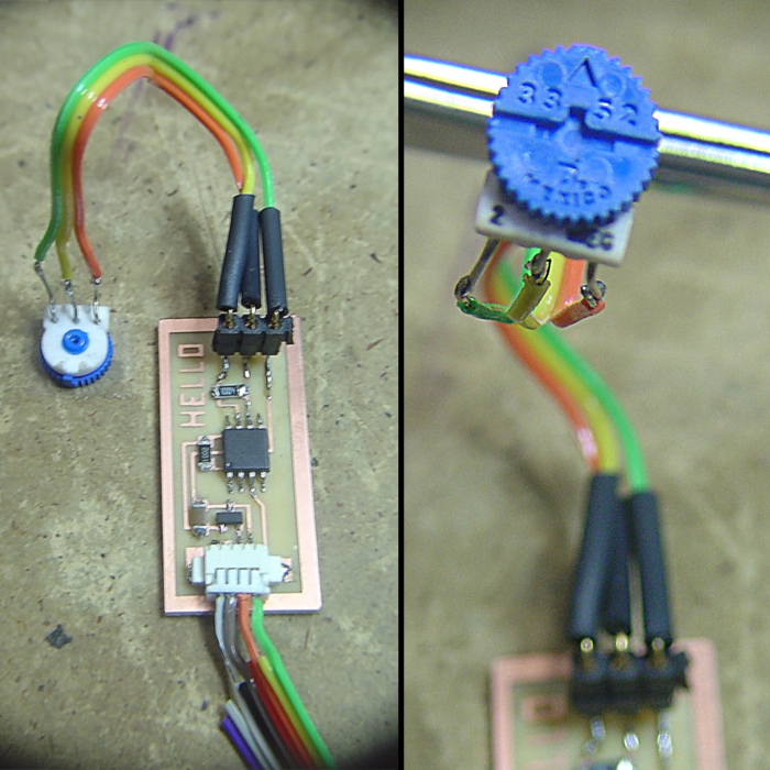
- connect the pcb to the computer using the serial cable
- browse to the class web page (http://fab.cba.mit.edu/classes/863.06/10.16/) and download the microcode and GUI code to the desktop (hello3.step.asm and hello3.step.py respectively)
- run the gavrasm assembler to compile your code
- in a terminal, browse to desktop and run“gavrasm hello3.step.asm”
- this will generate hello3.step.hex, which is the file type we need to load onto the microprocessor
- attach the parallel cable to the microprocessor, and run “avrdude -p t13 -c bsd -U flash:w:hello3.step.hex”
- remove the parallel cable (3M programming clip)
- run the python script to test the voltmeter “python hello3.step.py”
- modify/rewrite microcode and GUI code
|


