( h o w . t o . m a k e ) a low-cost, modular, networked video projector
gershon dublon
responsive environments group :: MIT media lab
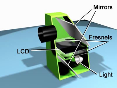
// goal For the final project I will design and build a modular, networked video projector, for under $40 in parts. The projector will be based around a microcontroller-driven LCD and high mcd LED, with optics cast in pdms or, if necessary, bought at low-cost. Internet 0 connectivity will allow the projector to communicate with other units in its vicinity, enabling applications for distributed projection such as automatic registration for higher-resolution display. There are several diy projector designs out there, but most use a re-purposed mp3 player or a full-size LCD from an existing device. The goal of this project is to design the projector to use commonly available standard parts, following the fablab's hello world tradition. // design My project will live somewhere between these:
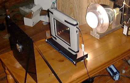
and this:
// components (updated 12/7) Color LCD: 128x128 Nokia Knock-Off, $11.96 (Sparkfun) Current total: $49.50 PDMS or Smooth-on Crystal Clear to cast lenses // processes
Microcontrollers
Networking Waterjet Lasercutting Molding/Casting // schedule Week of 12/7: Monday: finalize designs,
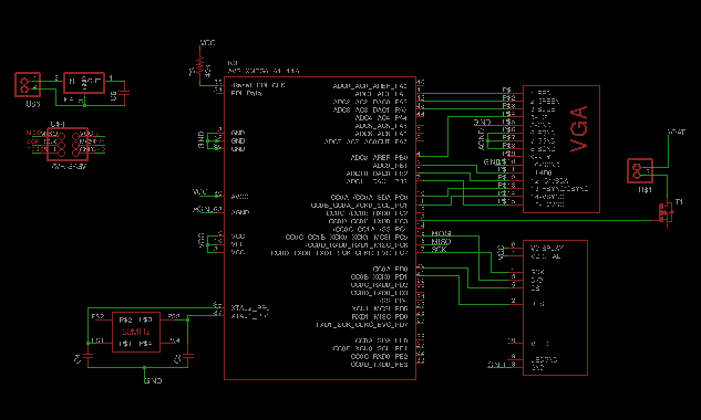
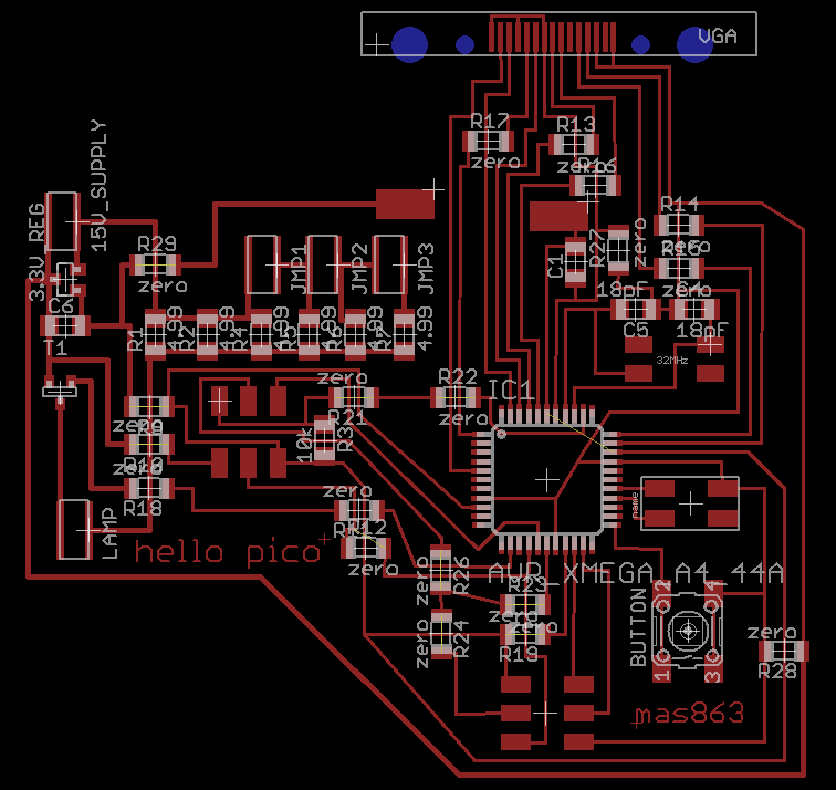
order more parts // project update: december 7, 2009 I went through a series of design iterations. Video is tricky with low-cost hardware; the trick is to think about the right balance of format, resolution, and framerate before doing any hardware design. I thought I had figured that stuff out last week, but I hadn't. To begin with, it turns out I was mistaken about the sample rate of the ADC on the ATMEGA644: it's 15ksps, not 200. Oops. That is not nearly enough (off by a factor of about 1000 from what would be ideal). That's when I moved on to the ADV7180 (10-Bit, 4× Oversampling SDTV Video Decoder). It looked perfect, until I read the spec of the video output format (barely referenced in the Analog Devices data sheet), ITU-R BT.656. Turns out it outputs 27Mbytes per second. Oops. Finally, I discovered the XMEGA microcontrollers. I hadn't seen them before, and their specs are perfect for my application. ATxmega16A4: Price: $2.50 in quantities of 100 I'm ordering a few of those today, and designed the board (below), so I can hopefully stuff tomorrow.
I started with the XMEGA design above. It took a long time to get it routed, and once routed, there were serious problems contouring the 10-mil pitch of the LCD SMD connector. The png DPI had to be high enough to distinguish between pins, but not so high as to crash cad.py (which took to seg-faulting after 30 minutes of hard labor). Eventually I gave up and made a small break-out board for the LCD.
And here it is after milling:
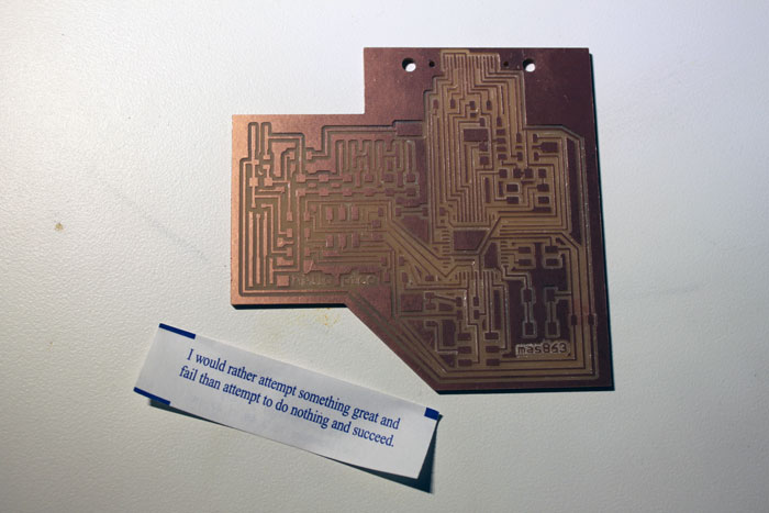
Once milled and stuffed, there were new problems, the biggest of which was the horrifyingly bad documentation for the new XMEGA chip. Usually Atmel is pretty good, but they really dropped the ball on this. For one, the datasheets all referenced JTAG support, but it turned out that my version, the 16A4, does not. The datasheet was vague about ISP support, ultimately claiming that the XMEGA requires a programmer that supports a new 2-pin interface, called PDI. This blog saved me in the end, showing how to wire up a regular old AVRISP to do PDI. Still, there's no documentation of that process from Atmel. Here's what I learned: AVRISP A few jumper wires and some hot glue later I was up and running:
But the problems weren't over. The new-ness of the XMega family meant that the documentation was bad AND there was very little existing code online. To test the chip I got a simple voltage-controlled oscillator going from this code. Good news: the board works.
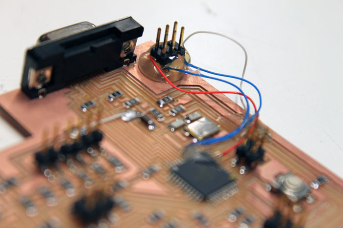
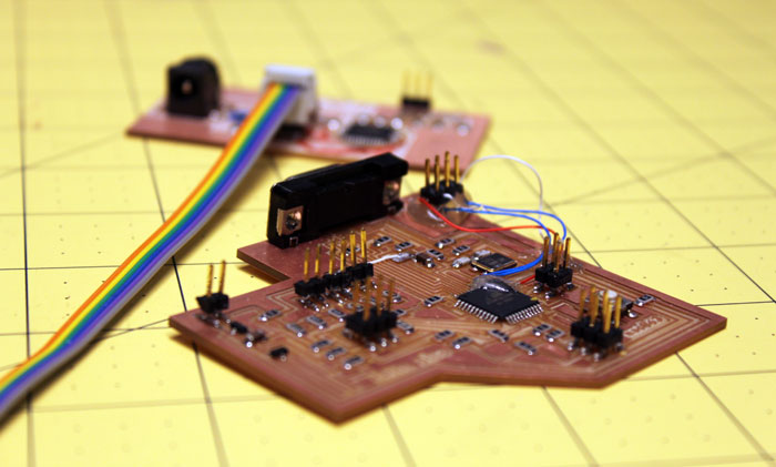
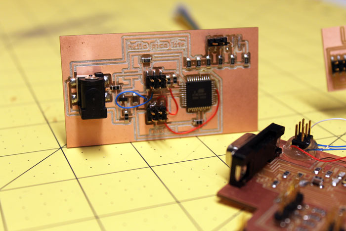
At this point (late night before the project was due), with little progress on the code front I decided to make a simper board to demonstrate the core concepts (just projecting something, if not vga). I designed, routed, milled, and stuffed a new ATMega644-based board faster than ever, before realizing I had missed a few pins on the microcontroller. Woops. One more design iteration later, everything checked out, but the micro refused to program. It took several hours of testing, googling, and wondering before I gave up and baked off the 644 and replaced it. Voila-- it programmed! Thanks David Mellis for the avrdude "-B 10" hint (that slows down the programmer). The new board, hello pico lite, was designed to run some example code from here, just to get started:
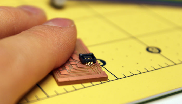
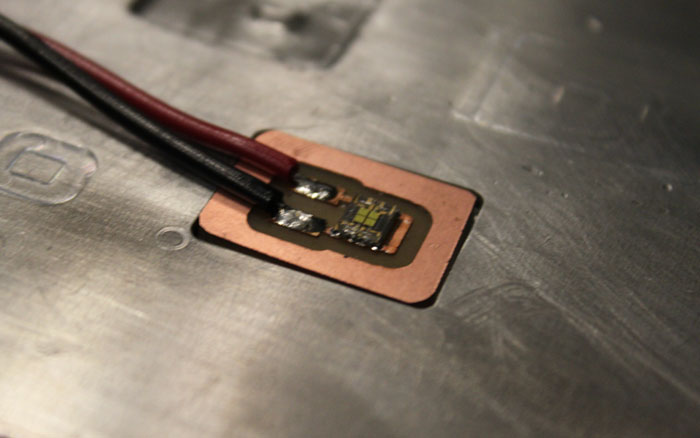
To whoever uses the Sparkfun eagle library for a Nokia LCD footprint: the pins are reversed! I fabbed and stuffed my breakout before realizing this, which was not easy, given the 9-mil pads on the SMD connector:
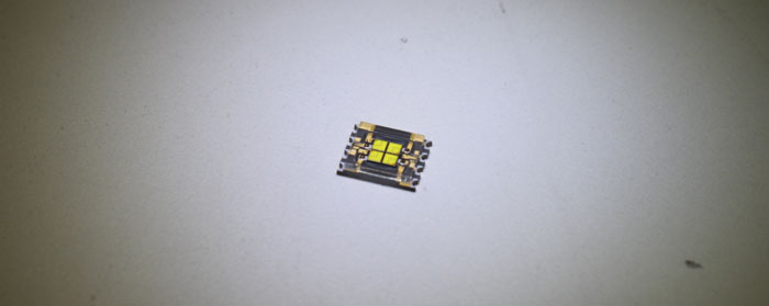
The next electronic component to deal with was the LED:
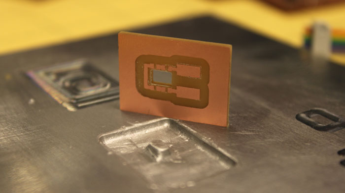
At 700mA, it puts out a healthy 560lm. This generates a LOT of heat, and requires serious heatsinking. Buying a board with a heat sink layer is expensive, but thanks to Matt in my research group, I decided to look into an alternative: fabbing an aluminum heatsink to snap right into a custom PCB and interface directly with the LED heat-slug through a layer of thermal grease.
Cad.py and the Modela were being uncooperative, so it took many tries to get it right. Eventually I did a single step in a z at a time, contouring in cad between each step, and it worked.
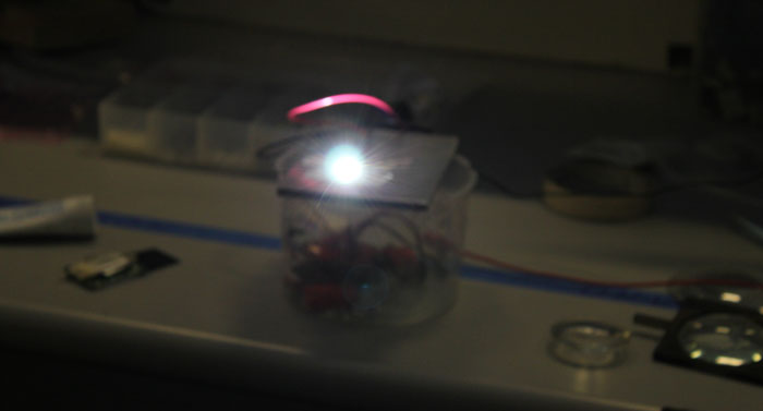
Finally fired up, the LED is insanely bright at 700mA:
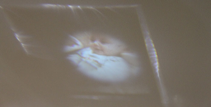
Finally, I could get a picture to show up somewhere (on the ceiling in ResEnv)!
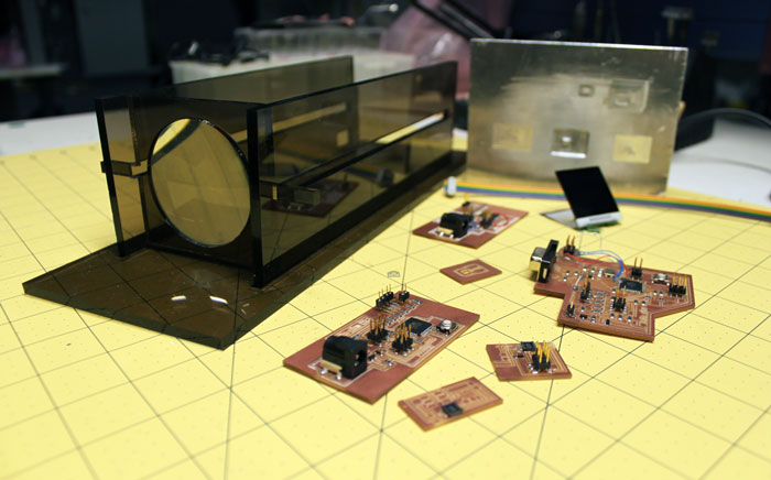
I didn't manage to get the full system integrated in time for the final presentation. The specs on the XMega are great, but as it turns out, building around new, relatively undocumented hardware requires more than a week. I'm still working on VGA as well as system integration, so expect updates here in the coming week.
materials: |
mas863 2009