DAVID A. MELLIS
MAS.863: How To Make (Almost) Anything
Week 11: Networking and Communications
IR LED and Phototransistor
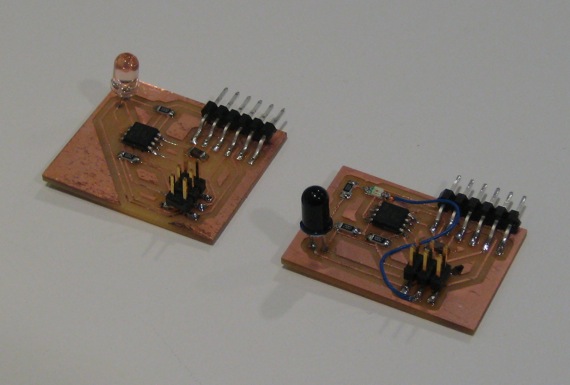
IR transmitter and receiver boards. The transmitter board (transmitter.sch, transmitter.brd) blinks an IR LED (irtx.asm) at a set frequency (~650 Hz). The receiver board (receiver2.sch, receiver2.brd) contains a phototransistor that it samples (freqrx3.asm) at twice the frequency of the blinking LED. It alternately adds and subtracts these readings to cancel out the ambient IR levels.
When the receiver boards detects the blinking IR LED, it illuminates its visible (red) LED. This works fairly robustly, and continues even if you point the transmitter away from the receiver. Unfortunately, it also works when I change the frequency at which the transmitter blinks the LED. I was hoping to be able to discriminate a particular frequency, but this doesn't seem possible using my naive sampling and filtering strategy.
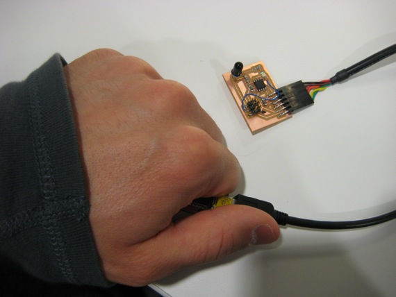
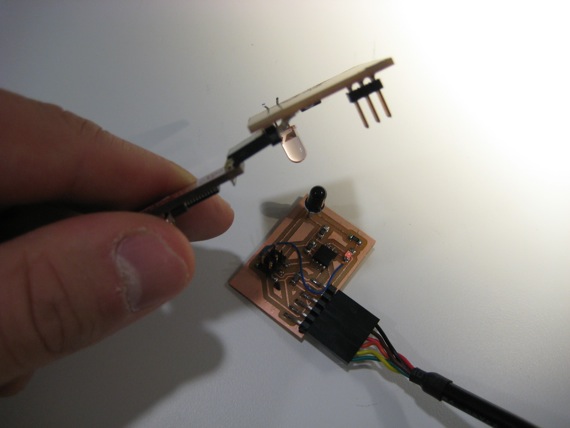
If I cover the IR LED completely, the receiver no longer detects it.
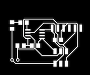


These boards were also a good opportunity to work with through hole components (the IR LED and phototransistor). I exported three PNGs from Eagle: one with the top and pads layers (milling the traces with a 1/64" endmill), one with just pads that I flood-filled white in the Gimp leaving just a black dot for each hole (milled with a 1/32" endmill), and one with a bottom layer rectangle for the dimension (1/32" endmill).