DAVID A. MELLIS
MAS.863: How To Make (Almost) Anything
Final Project
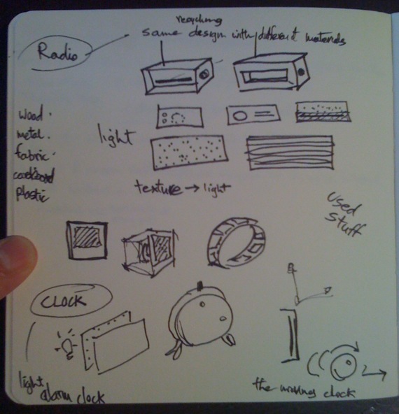
Fab Radio w/ Found Materials
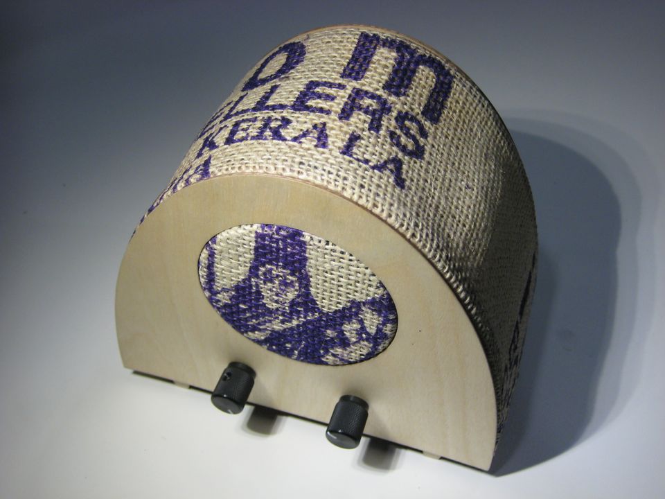
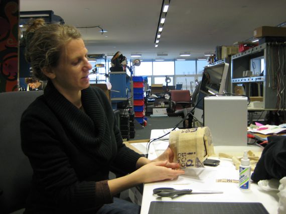
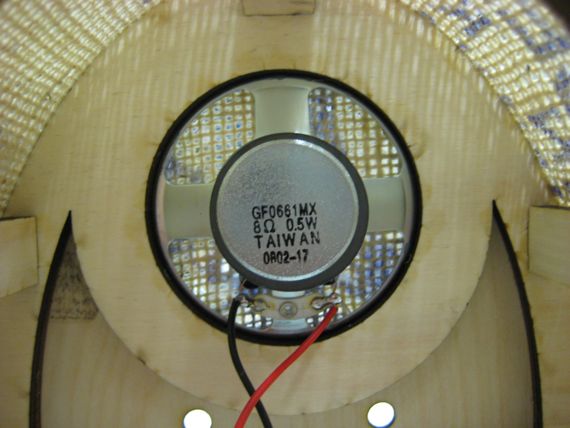
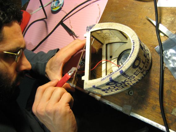
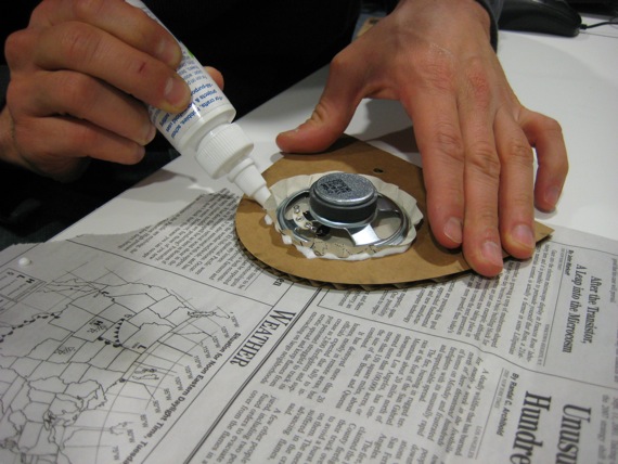
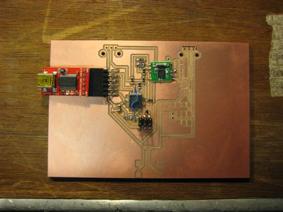
This radio, created in collaboration with Dana Gordon, is an experiment in the fabrication of consumer electronic products. The frame is made of press-fit, laser-cut plywood and covered with thin front and back face-plates. Any found material can be used for the fabric, which covers the top of the radio and the speaker. Here, we've used a souvenir from a trip to India. The electronics, including knobs and power jack, are mounted on a single circuit board at the base of the radio. The whole product is designed to be easily and quickly assembled from fabricated components.
There are numerous examples of individuals producing circuit boards or electronic kits in quantities of hundreds or thousands, but few target a general audience. By carefully designing the appearance and construction of the radio's case as well as its electronics, we have arrived at a consumer product that can be manufactured in similar quantities. With access to a laser cutter, an individual could manufacture and sell this radio on a scale sufficient to provide significant income. We hope that this example will help inspire the creation of fabrication-based, consumer electronics small businesses.
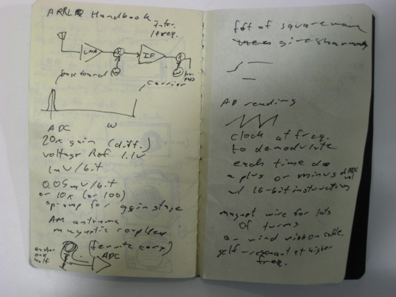
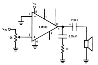
Simple audio amplification circuit using an LM386 (built-in 20x gain) w/ a 0.1 uF capacitor to remove the DC current from the incoming signal. Will be replaced with a milled PCB. I omitted the volume potentiometer for now, so it's really loud. There's also lots of static, but that's probably because the new Media Lab building is a big metal box.
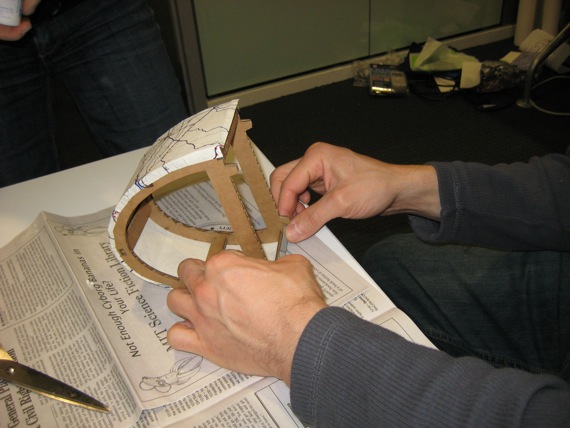
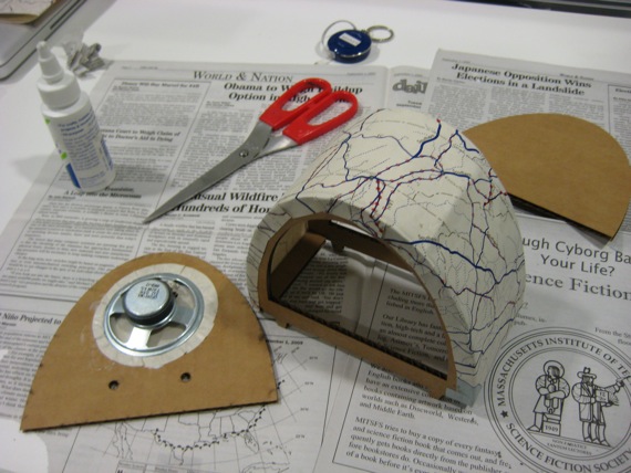
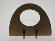
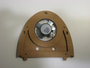
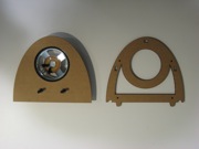
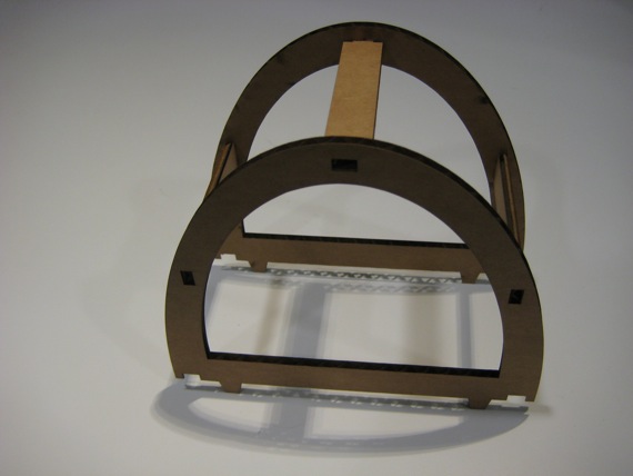
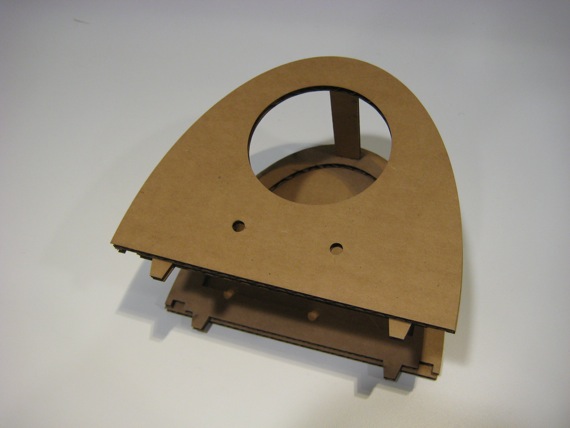
Redesigning the structure. The front panel has bigger holes that fit the potentiometers. The front frame has a hole that's slightly smaller than the speaker and will hold it in place.
Download: radio4.svg (Inkscape).
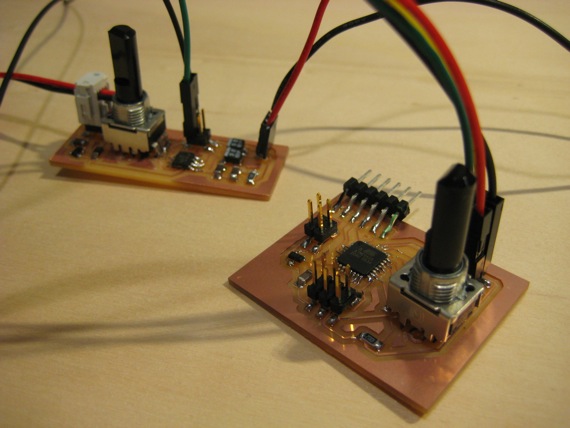
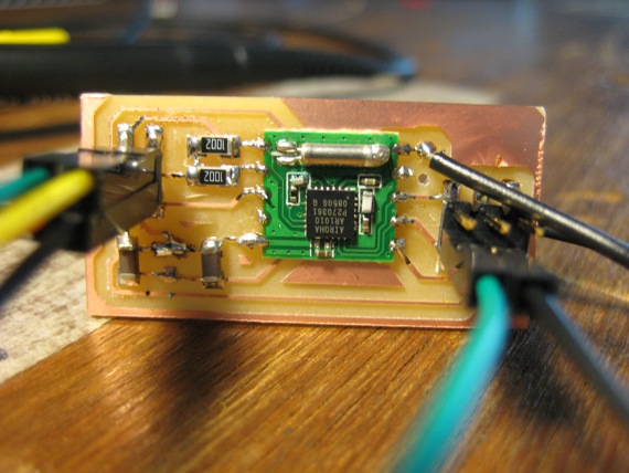
Two new boards: one for the ATmega88 and the other for the amplifier (LM386). I've added a volume knob and another potentiometer than can be used for tuning.
Download: atmega88-2.sch, atmega88-2.brd
Download: amplifier2.sch, amplifier2.brd
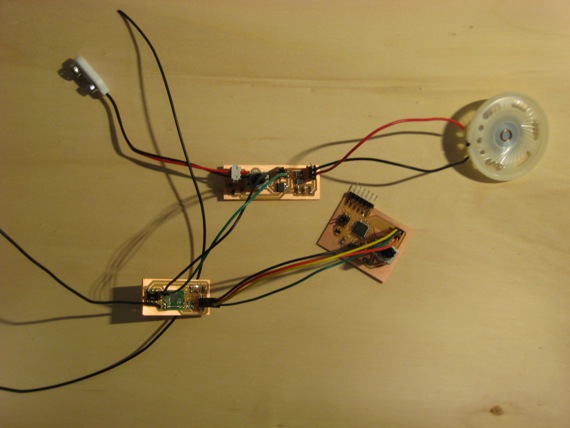
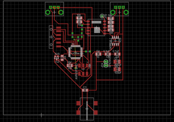
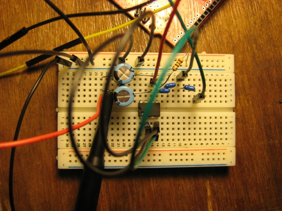
Integrating the three circuits into one PCB. The potentiometers should align with the holes in the front panel, and the power jack with a hole in the back.
Download: combinedsmall.sch, combinedsmall.brd
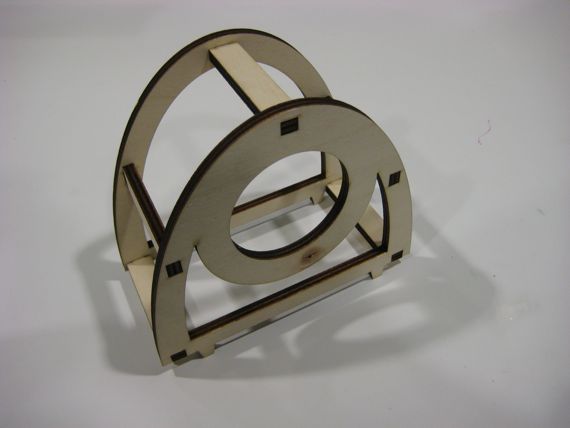
Laser-cut 1/4" plywood in a pressfit structure for the radio frame.
Download: radio-0.25-inch-plywood.svg, strut-0.25-inch-plywood.svg (Inkscape)