DAVID A. MELLIS
MAS.863: How To Make (Almost) Anything
Week 3: Milling
Making PCBs on the Modela
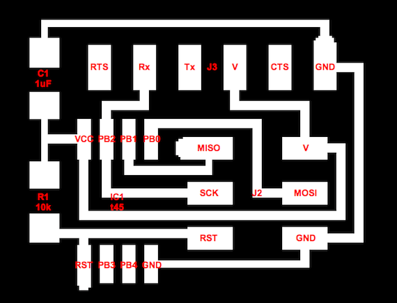
Screenshot of my hello.ftdi.45.cad.
I modified the hello.serial.45.cad so that I could use it with my existing USB-to-Serial (TTL) convertors. This meant replacing the 4-pin serial header with a 6-pin one, and removing the voltage regulator (because my convertor provides a regulated power supply).
Download: hello.ftdi.45.cad
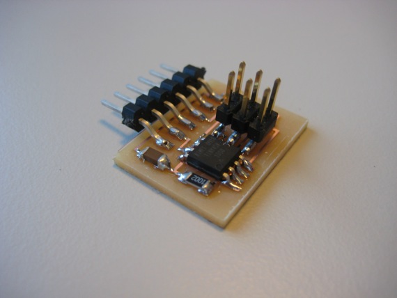
The assembled PCB.
Milling the PCB on the Modela and stuffing it was relatively straightforward. My soldering was not the best (it's my second time with surface mount components), but everything worked on the first try.
Some lessons:
- Even though they say that the Modela bit doesn't have to be super tight, if it's too loose it will slip while milling. A couple of times, the bit stopped milling and when I stopped the job, it slid out of the collar.
- Changing the bit on the Modela requires a bit of manual dexterity. Not much, but enough to make it non-trivial.
- If you don't mind rougher edges, you can cut out the PCB on the board cutter (the big machine in the hallway) rather than the Modela.
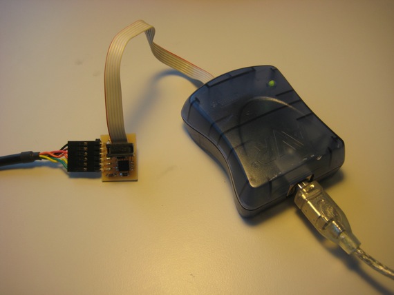
Programming the ATtiny45 with an AVRISP mkII.
The ATtiny45 on the PCB can be programmed with any ISP (in-system programmer). I'm using the AVRISP mkII, which you can get for $35 from Digi-Key. The colorful 6-pin header is part of an FTDI USB-TTL Serial Cable, which provides a regulated power supply and serial communication ($20 from Digi-Key).
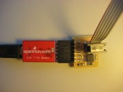
You can also use an FTDI Basic Breakout board from SparkFun ($14) instead of the FTDI cable:
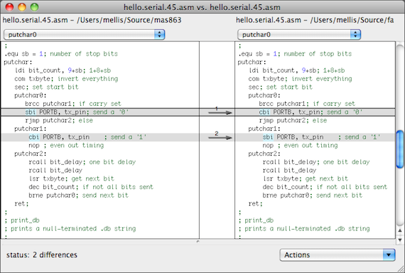
The two small changes to the hello.serial.45.asm file.
Because the original hello.serial.45.cad board has no line driver, it inverts its serial output (i.e. uses 5V for 0 and 0V for 1). I had to modify the assembly code to output non-inverted bits.
Download: hello.serial.45.asm, hello.serial.45.hex
To compile my program, I used avra, which should be compatible with Atmel's avrasm (Windows-only). The recommendation for Linux, gavrasm, doesn't provide Mac OS X binaries (and it's written in Pascal, which made me reluctant to attempt to compile it). I had to copy the ATtiny45 board definition file from AVR Studio on Windows.
Download: tn45def.inc
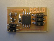
The assembled hello.serial.45.cad board.
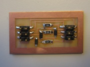
The assembled dasa.cad board.
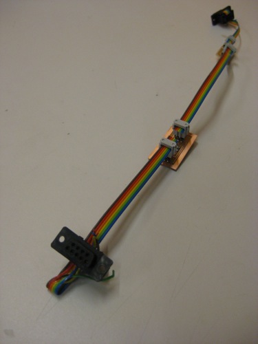
The two boards and programming cables.