 Weightlifting Power Meter
For my final project I decided to make a weightlifting power meter.
Goal/Motivation
In case you couldn’t tell from my decision to 3D print gymnastic rings, I have become quite fond of CrossFit workouts. One important aspect of CrossFit is quantifiable proof of increase in performance. The most important quantity to a CrossFitter is power, often referred to as intensity, and easily given by the equation (force x distance)/time. High level cyclists have been using power training for some time now, but the concept is just starting to come around in weightlifting/power lifting. The reason it has taken longer is partly due to the fact that measuring power output for a bike is slightly simpler and less intrusive than measuring power for a weightlifter, and mainly because the only systems currently available cost >$1000 (http://store.sorinex.com/Tendo_FitroDyne_p/t-1.htm). Being able to measure power output during lifting not only gives a great metric for showing increased performance, but also highlights the weight at which an athlete produces the highest power (see the graph below). This is very helpful in ensuring proper weights and repetitions are chosen for future workouts in order to best increase strength and velocity performance.
Source: http://www.fitronic.sk/fitrodyne_basic.htm
People want the product, but not for that much money. I also want one, but I’m going to try to make it instead of buying it, and for substantially less cost.
Design
My weightlifting power meter will consist of two components. The first component is the measurement device. It attaches to the object that is going to be moving (usually a barbell or dumbbell but could also be attached directly to a person), must measure the distance/time component of the power equation, and communicate with the base station. This can be done in a variety of ways. Instantaneous velocity, total distance traveled along with a start time and stop time, or acceleration could all be measured. The FiTROdyne (shown at the top of this page and directly below) attaches a string to the moving object and measures instantaneous velocity from the movement of the string. I’m also attaching a tether.
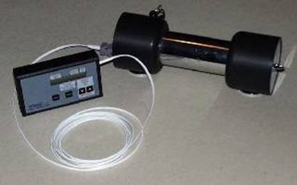
Source: http://www.fitronic.sk/fitrodyne_basic.htm
The second component is a small base station with an LCD and
some buttons. This allows the user to
set the weight that is being used, turn the system on/off, reset the repetition
counter, and view the output. The basic
FiTROdyne layout is below.
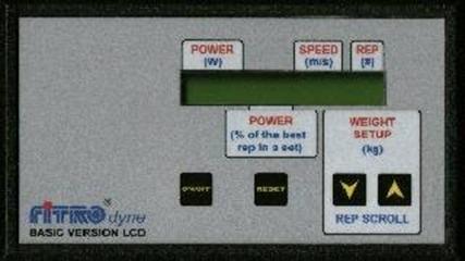
Source: http://www.fitronic.sk/fitrodyne_basic.htm
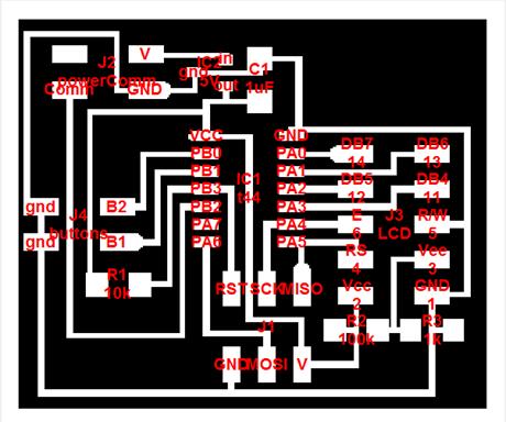
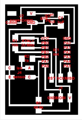
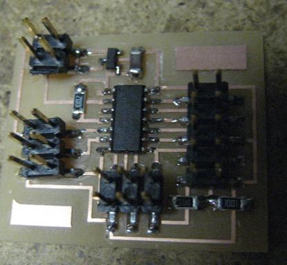
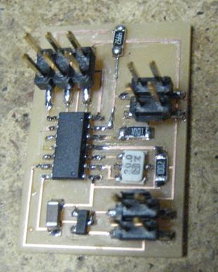
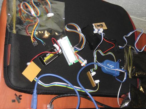
I designed my two boards in cad.py. All components are from the standard FabLab inventory.
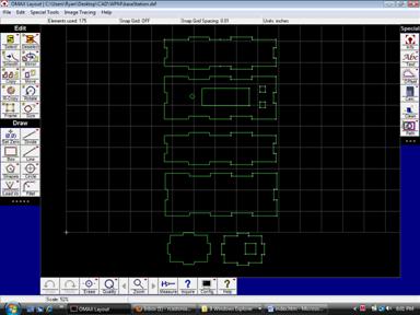
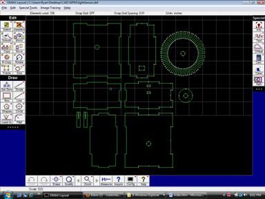
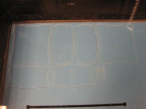
I designed the base station and light sensor housing in OMAX Layout and used the lasercutter to cut .125” acrylic. They’re pretty neat press-fit structures.
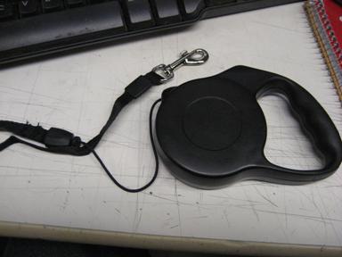
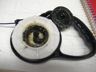
I spent quite a bit of time trying to figure out how to get my tether to automatically retract into the housing without putting much more than a negligible load on the lifter. A clock spring seemed to be a good idea but unfortunately nobody could tell me how to properly size one so I didn’t know what to order. Instead of ordering and assortment and testing them out, I just tried to think of an existing commercial product that extends about 10’ and automatically retracts without applying too much force. I figured a tape measure would be pretty tacky but then I realized the perfect component….a small retractable dog leash!
Components
All purchased components (with the exception of the dog leash) are standard FabLab components.
2 –
attiny44
1 – LCD
2 – push buttons
1 – LED
1 – phototransistor
1 – on/off switch
2 – 5v voltage regulators
2 – 1 uF capacitors
1 – 1k resistor
1 – 10k resistor
1 – 49.9k resistor
1 – 100k resistor
2 in – 5/32 tubing (for axle)
Headers and cables
.125” acrylic
Processes
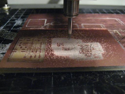
I milled my boards out on the Modela.
As I expected, I spent a large amount of time figuring out the micro code. Big lessons learned:
-The pins on the same port as the LCD that aren’t being used by the LCD seem to flip randomly. I originally attached buttons to them and couldn’t get them to work. I re-routed my board and only used PORTB pins (LCD on PORTA) and everything worked fine. Weird.
-The HelloLCD code only shows how to print strings and the decimal ASCII characters. I utilize lcd_putchar to use registers to write the ASCII characters.
-Double check your timing on your components if you want them to talk. While there is a 20mhz XTAL on my light sensor board, I’m not actually using it because I want the boards running at the same speed. I might fix this later.
Here are the acrylic press-fit housings for the base station and light sensor. They’re .125” thick. I cut at 100% power and 4% speed.
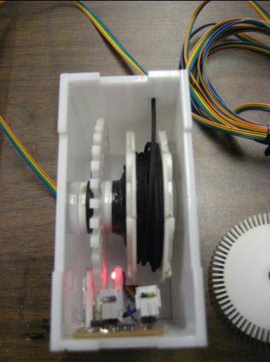
I originally planned to cut slits in the dog leash component and use that as my rotatry encoder, but there wasn’t enough clearance.
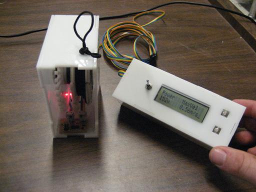
The base station coming together…
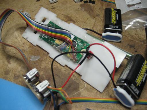
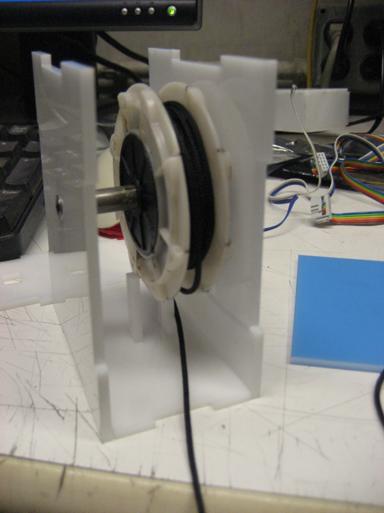
Mounting the LED and phototransistor
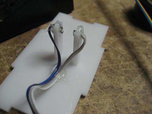
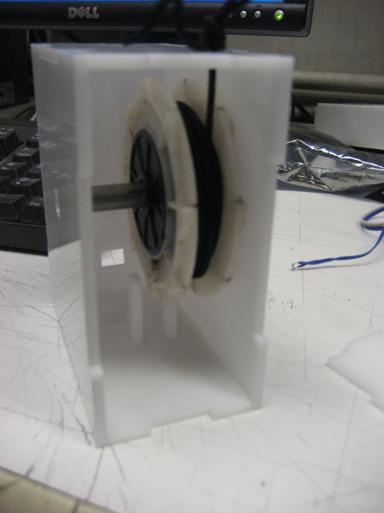
The completed sensor housing.
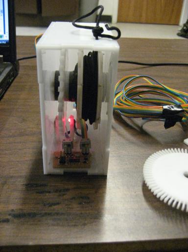
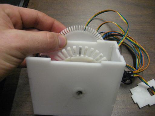
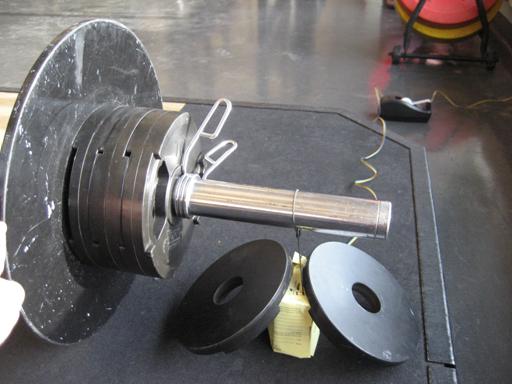
My original rotary encoder
was designed to provide me with 1 cm/sec accuracy when sampled every .25
seconds. Unfortunately the teeth were
too small to fully block the LED. I cut
the number of teeth in half. Now I have
2 cm/sec accuracy when sampling at .25 seconds.
Still pretty good if you ask me.
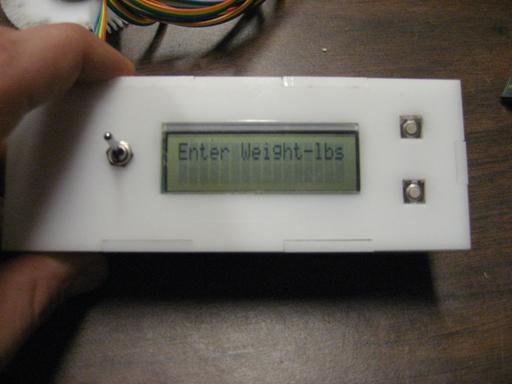
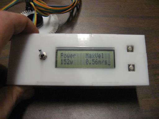
Completed base station at startup screen
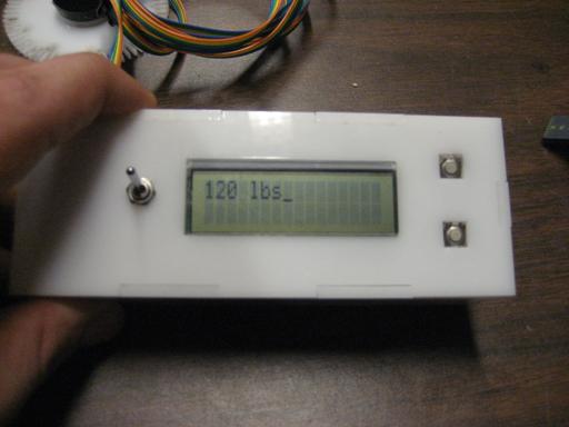
Top button increases weight and bottom button decreases.
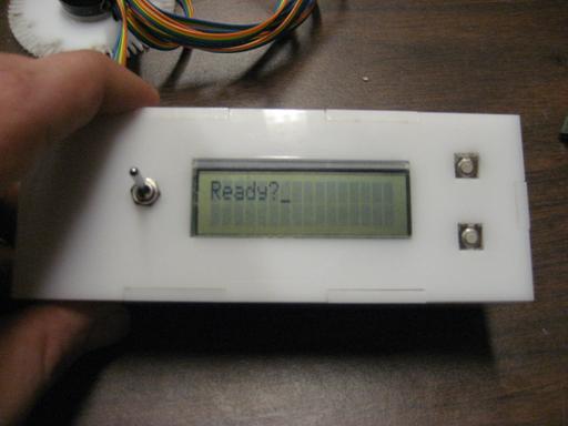
Timer interrupt asks if you’re ready. Top button is yes and it looks for a velocity from the light sensor. Bottom button is no and let’s you keep adjusting the weight.
Output screen after a lift. Top button looks for the next lift. Bottom button lets you change the weight value.
It works!!!
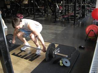
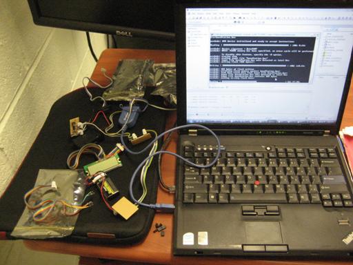
Testing setup at the gym. The sunlight was getting through the acrylic and resulted in inaccurate readings from the phototransistor. We had to make a quick photon shield (paper).
Results…