I was really busy with other things this past week, so I thought I'd do something fairly simple for this week's project (I already did motor control using an H-bridge and PWM in week 2 and built a speaker circuit for week 6).
My idea was to take my synthesizer circuit, remove the resistor ladder DAC, and use high-speed PWM to drive the speaker. I thought I'd try to go a step further than the example design and make it a proper class-D amplifier with push-pull drivers and a low-pass filter to remove the PWM carrier frequency.
It was supposed to be a quick modification to an existing circuit, but things don't always work out when I try to design analog circuits...
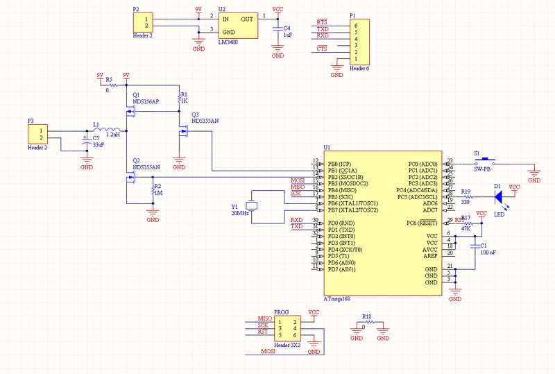
Above is the schematic for the circuit I tried to make. The speaker is pulled both to high and low voltages by a pair of complimentary MOSFETS, so current is driven through it in both directions, rather than just pulling it one way and letting it go. Since the microcontroller can't output a high enough voltage to turn off the P-channel MOSFET, the gate is pulled up to the 9V battery with a resistor, and an N-channel MOSFET pulls the gate low to turn on the P-channel MOSFET. The NMOS device that controls the PMOS and the NMOS device that drives the speaker low both have their gates connected to output compare outputs for timer 1 on the mega168, which are set up to output inverted signals, so the P-channel MOSFET is on when the N-channel MOSFET is off, and vice versa.
The inductor and capacitor form a low-pass filter with a corner frequency of about 16 kHz, filtering out most of the PWM carrier while passing the audible frequencies.
In the schematic, the P-channel MOSFET is backwards (should have its drain and source flipped.) This was what caused the first of my problems, and I didn't notice it until this morning.
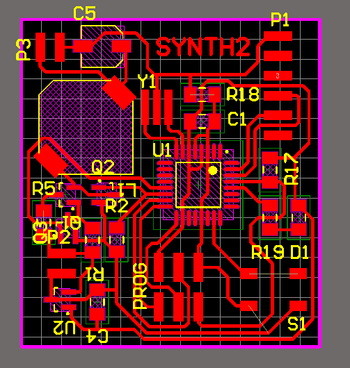
One thing I noticed before machining my boards this week was that if I have my design rules set to allow a 16mil minimum space, and I export the board image at 1000 DPI, parallel vertical or horizontal traces at the minimum spacing are fine, but some parallel diagonal traces at the minimum spacing will get merged together. I might set my design rules to require a slightly larger space in the future just to be sure this doesn't happen.
The first problem I ran into was that the P-channel MOSFET wasn't turning off. I spent a bunch of time debugging, but didn't catch the problem until this morning (the P-channel MOSFET has its drain and source backwards.) I did catch that the pull-up was a bit too weak and the rise time for the gate was slow, and made the switching on the gate look a lot nicer by using a much stronger pull-up, but that obviously didn't fix the problem with the MOSFET being backwards.
In my debugging, I gave up on trying to use PMOS and switched the high-side driver to N-channel, using the 9-volt battery and a pull-up to switch the gate at 9V, and driving the speaker from only 5V (from an external power supply since my on-board regulator couldn't source enough current for the speaker.) That worked well enough to get good sound, but there was still some time during switching where both MOSFETs were on and shorted, so they drew a lot of current and got hot. The amplifiers that employ this technique usually have some way of ensuring that there's some dead time between one MOSFET switching on and the other switching off to ensure this doesn't happen. The tiny45 has this feature (for being such a small chip, it has a lot of great features) but the mega168 I used does not.)
To get the circuit working, I removed the whole output stage except for one N-channel MOSFET, so it's basically the circuit from the example board and the speaker is only being driven in one direction. It works, and it doesn't really sound any worse than when it was operating as a push-pull amplifier. I also removed the low-pass filter. It made the waveforms look more like audio on the scope, but with the speaker connected it didn't really make any difference in the sound. So, all of my effort wasn't really worth it... the single-MOSFET driver sounds fine, at least for the kind of audio one can generate with an 8-bit microcontroller.
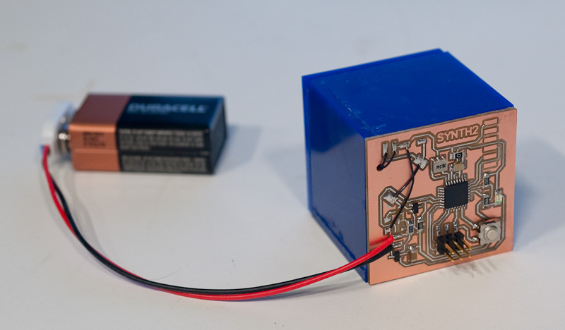
To make the speaker louder, I built a lasercut acrylic box for it. I sort of ran out of energy and glued it (and my fingers) together in a hurry, so it looks like a superglued mess, but the box has a huge effect on the sound. It gives the speaker a lot more volume and better low-frequency response. The circuit board forms the back of the box.
