In-System Programmer for AVR MCs
Acknowledgements
I'd really like to thank Brian Mayton for his help with helping me debug this ISP. Had he not pointed out that I messed up resistor values, I'd probably still be sitting on the 5th floor debugging this thing.
Related Links
Eagle File: fabisp.sch
Eagle File: fabisp.brd
Schematic: fabisp.pdf
PNG: fabisp.png
PNG: fabispdim.png
Firmware: firmware.zip
“On the rainbow scale of fabulous, FabISP is pretty much in the gold pot.”
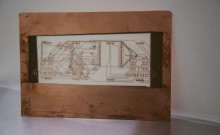
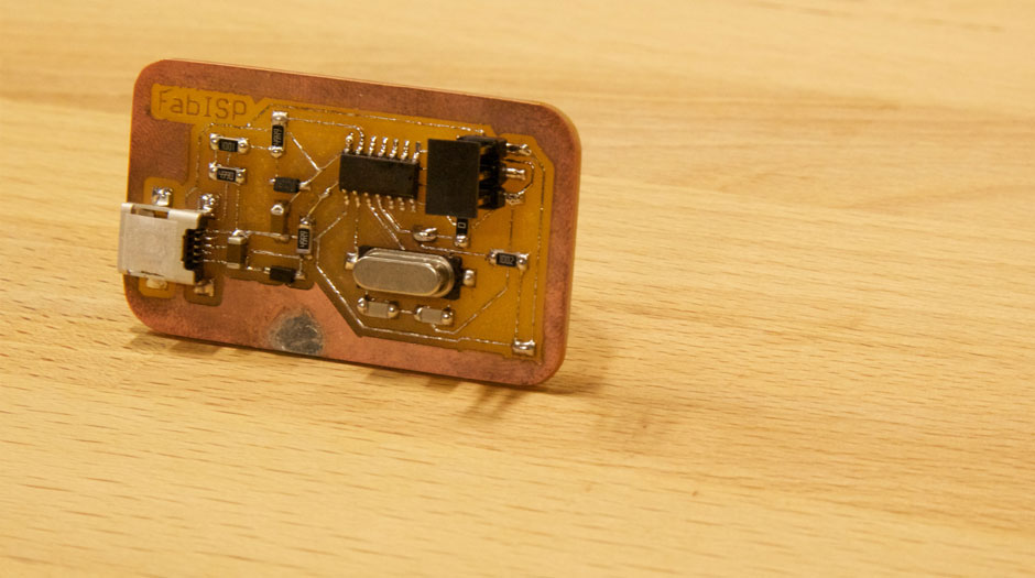
The FabISP is an in-system programmer for AVR microcontrollers, designed for production within a FabLab. That is, it allows you to program the microcontrollers on other boards you make, using nothing but a USB cable and 6-pin IDC to 6-pin IDC cable. It’s based on the USBtiny and V-USB firmwares, which allow the ATtiny44 to perform USB communication in software. Programming can be done through avrdude. The schematic (PDF) is super simple: USB connector, ATtiny44, and 6-pin ISP header, with assorted passive components. I started with the Eagle files for the USBtinyISP, although there’s almost nothing left of it. Most of the parts for the FabISP are in the FabLab inventory. Exceptions include the Mini-B USB connector (SparkFun, Digi-Key), 12 MHz crystal (Digi-Key), and 18 pF capacitors for the crystal (Digi-Key).
Design
The in-system programmer I’m using is MIT’s FabISP design. It’s designed to be fabricated in fabrication lab with minimal work. On the rainbow scale of FABulous, FabISP is pretty much in the gold pot. You can get the needed files by following the links on the left. Once you have those files you’re read to fabricate the board using the Center for Bits and Atoms Fab modules.
Fabrication
You can fabricate the printed circuit board one of two ways in the lab. One way is to use the vinyl cutter to cut a copper sticker in the shape of the circuit and paste it onto a surface when completed. The second and more robust way to fabricate a circuit is to mill one from copper coated circuit board. This is quite easy. You take the eagle files and you can feed it in to camit.media.mit.edu where they will return file that the mill can read. This file will tell the mill where to move so that your circuit can be created exactly like the design.
Next you use two sided tape to tape the copper coated board down the the milling surface. When that’s done, you zero the mill by hand. In the lower left corner of the plate you set x and y to 0. Then you turn on the drill and lower the mill by .001 inches each press until you see a speck of copper fly up, meaning the mill has barely touched the surface. Now all that’s left to do is press play on the milling software. The milling process is depicted below. First on a $2500 Roland Modela powered by an Intel Core 2 Duo. The second has no processor, is made of wood and cost $100. Oh, did I mention it’s 2-3 times faster than the Roland Modela and just as accurate?
Assembly
I assembled the entire board before somebody told me about Flux. I want those hours of my life back. Had I known about this magical substance, I would have finished in 20 minutes with a perfect board. Instead, after soldering everyone to the copper circuit, I was left with an unprogrammable board. Flux allows the solder to adhere to the copper and avoid the board. It changes the properties of the metal so that less is needed and your soldering is more accurate. It’s about $9 a pen for anybody that’s interested.
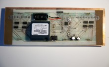
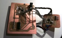
Assembly consists of soldering resistors, capacitors, the ATmega microcontroller, a mini-usb and a few other misc components to the board. It’s fairly straight forward if you follow the circuit diagram. When finished, you can attempt to program your board.
Programming
To program your board, you need an already working MC board. You download the firmware and hook up your board to another ISP. Then run the commands in terminal that will send the firmware to your board. If everything works, you’ll get a message telling you of your success. If not, you’ll get one of these: “Error 1: Check connections.”
Debugging
As most students did, I got an error 1 right out of the gate. I rechecked the circuit diagram with my board and Brian pointed out that I had a 499 instead of a 49ohm resistor. After swapping out the resistor, everything worked like a charm. The board was able to be programmed and recognized over mini-usb.
Tips
There are several small traces that run under resistors and capacitors. Be sure that you keep your solder clear of these so you don’t accidentally create a short. If you do, finding these locations can be a real pain.
Also, I can’t recommend FLUX enough. It helps! Use it!
