Week 5: Programming Microcontrollers
This week was a return to the electronics of two weeks ago, only this time it was a little more open-ended! This week we made a very simple circuit board with an ATtiny44 that ran an LED and a button and could do something. I found that the fabrication part was fairly straightforward, but I have very little programming experience and so that was definitely more challenging for me. I've tried to explain the programming aspect of this project with particular attention, because I couldn't find a complete set of instructions that clearly lays out what you should do.
Designing the Board in Eagle
This week the board design was not given to us, but we had to modify an existing design to include an LED and a button. I used Eagle freeware to do this (you can download it at www.cadsoftusa.com) and it was pretty straightforward. Eagle works with two dual windows - one is for the schematic of your board (where you decide what components you will use and how they will be connected) and one is for the layout of the traces on your board. Note that you need to keep BOTH OPEN AT THE SAME TIME for changes in one to apply to the other. If you forget and close one window, just restart the program because it won't be able to make changes to both files if they're not simultaneously open. During our Eagle tutorial, I kept notes which you can find here.
Also, here are my board schematic and layout if you want to use them or modify them for your own purposes!
Milling and Stuffing the Board
The process I used this week was identical to what I did in making the FabISP. The only problem I encountered was with cutting the outline of the board on the Modela. In Eagle, the outline is shown by default as a line of width 0, which I didn't realize so when I tried to create a path, the fab modules couldn't make one. So I changed the outline to have a width of 0.01" by right-clicking on the wires that make up the border and changing their properties.
After this I had another problem in that the outline was too close to my traces, and it removed all of my ground traces on one side. I tried making the wire size on Eagle smaller (originally I had it set at 0.32") but this made no difference, so I tried enlarging the size of my board's outline and then centering the traces within the larger square. This worked, although in future with more complex boards that would take longer to resize this way, I may just mill out the traces, and then use a press to cut it out, as Adam Setapen suggested.
Stuffing the board was also straightforward, but a couple of things to note about the new components I used:
- The green/colored line on the LED points AWAY from the microcontroller. (Orientation matters for diodes.)
- When soldering on a 20.0 MHz crystal, don't start with a solder tack that is underneath the crystal - put it on the side, next to where you're going to put the crystal. If you put it underneath, then the crystal can't lie flush with the board.
|
|
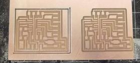
This is a picture of the cut the Modela made to outline my board - I don't know why there is an inner and outer path, but it definitely caused me some problems. |
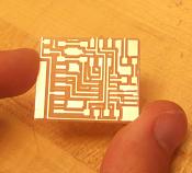
If you look at the top portion of this board, you can see the that the trace for ground has been completely removed by the outline cut. |
|
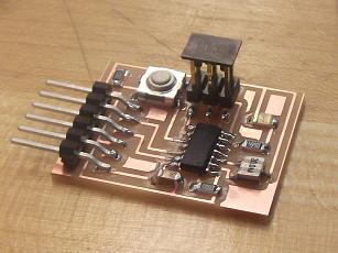
The completed board after stuffing. |
Programming the Board
So this is where it gets tricky. The first thing you need to do if you're a Windows user is download drivers for your FabISP: the drivers can be found here and once they're downloaded, then you need to point the Windows program that's searching for drivers (its a futile search without this download, by the way) to this file. Once you have done that, then the FabISP can be recognized by your computer and it can upload programs to your board.
You will also need to obtain an FTDI cable so that your board can communicate with your computer and get programmed.
Using Arduino
You can write and upload programs using several different platforms. The most straightforward for me was to use Arduino software - this creates a program in C and can be used to upload programs to your board. The Arduino software I used also included sample programs which I modified, since I have very little programming knowledge. David Mellis has developed a great tutorial and Arduino software that I used, and it can be found at hlt.media.mit.edu, under Tutorials. The workflow is:
- Open the Arduino software and write a program.
- Connect your FabISP to your computer, connect the FabISP to the new board with the rainbow cable, then connect the new board to the computer using an FTDI cable.
- Under Tools -- Board, choose the microcontroller that is on your board (I used an ATtiny44).
- Under Tools -- Programmer, choose USBtinyISP (or a different programmer if you're not using your FabISP.
- Click the Upload button to upload the program to your board.
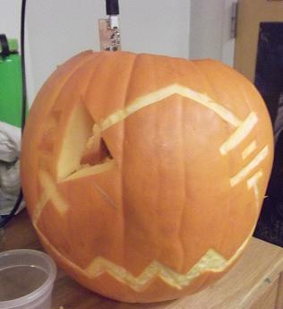
You can see my program here; I modified the basic Blink program to blink the LED to spell out "Sup" in Morse Code. Also, because it was Halloween this weekend, and because one of my roommates is a Course 6 major, our entry in the pumpkin carving competition got a definite boost from this project! (See photos below!)
|
A masterpiece thanks to some artistic talent and some serious circuitry (notice how the circuit contains an LED in series with a resistor and voltage source)! |
Using WinAVR and C
We were also asked to program our board without an IDE like Arduino, so I used the basic WinAVR package that we first used in Week 2. I set up the connection between the boards the same way I did for the Arduino workflow above. Here's the workflow:
- Download WinAVR (this is for Window's users).
- Write a program in C.
- You will need a Makefile that can compile your C code into a .hex file, that is finally transferred to your board. There is a standard Makefile that you should open in Wordpad (not Notepad, the lines are all smushed together in Notepad) and then modify - here's mine. The only modification you need to make is to enter the name of the C file that you wrote for the Project name (its the first line). Make sure you save the Makefile in the same place as the C file you wrote.
- Open Cygwin Command Line and navigate to the folder containing your C file and Makefile. Then enter the following series of commands:
- make -f [FILENAME].c.make
- make -f [FILENAME].c.make program-usbtiny-fuses
- make -f [FILENAME].c.make program-usbtiny