contact // irina chernyakova
1 [0912] FINAL PROJECT PROPOSAL 2 [0919] COMPUTER CONTROLLED CUTTING 3 [0926] ELECTRONICS PRODUCTION 4 [1003] COMPUTER CONTROLLED MACHINING 5 [1010] FINAL PROJECT UPDATE 6 [1017] MOLDING / CASTING / COMPOSITES 7 [1024] EMBEDDED PROGRAMMING 8 [1031] 3D SCANNING + PRINTING 9 [1107] INPUT DEVICES 10[1114] INTERFACE + APPLICATION PROGRAMMING 11[1121] OUTPUT DEVICES 12[1128] MECHANICAL + MACHINE DESIGN 13[1205] NETWORKING + COMMUNICATIONS 14[1212] FINAL PROJECT DEVELOPMENT 15[1219] FINAL PRESENTATIONS
1 press/fit/kit
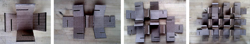
The assignment for this week is to create a press fit model using computer controlled cutting. The laser cutter, as a machine, allows for precision – reducing waste, eliminating the need for adhesives, etc. The assignment speaks to understanding materiality, that is, material thickness, strength, its particulars. For a simple assembly, I thought about an unfolding a box, and after several tests, came up with a unit with four pinhole notches that would allow for aggregation of a single type of module and expansion in the x, y, and z axes.
laser bed (24x36) / conserve material (and remember to always carry a camera cord!)
1
/ 2 / 5 / lots ..
the
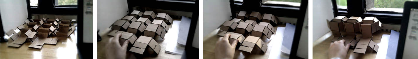
simple x-cross connection allowed for flexibility in the construction
of the whole; the units could collapse and expand, in the x, y, and
z.
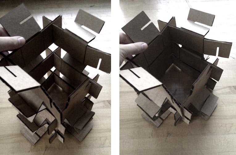
collapsible
tower?
1a notes/
epilog laser cutter, 120W
corrugated cardboard
cut/ power 25, speed 65
score/ power 10, speed 90
Make sure to test the connection between two units; chamfers help // Using parametric software that has control of the notch size would be incredibly helpful – in this case, it wasn't entirely necessary since a single unit was repeated, however, that type of control and workflow would be beneficial for future projects // allow time for development, the efficiency and speed of the laser cutter could allow for a very tight feedback loop between modeling and making – it is much more helpful to cut an initial set of units, test its potential, and then return to modeling. Work back and forth between digital and physical.
2 workflow/parametric beginnings?
I began to create files and a workflow for a basic waffle structure, a simple bulge. I started to learn grasshopper, and would like to understand it can be utilized in the context of press-fit kits (thinking of how to make something big.) A simple script allows one to create notches at the intersections of two planes within a 3d model. The script allows the user to specify the width and depth of the notch. [see example here] [and here] I'd like to understand this workflow (initially orthogonal x/y intersections, to more complex/less defined) - updates to come.
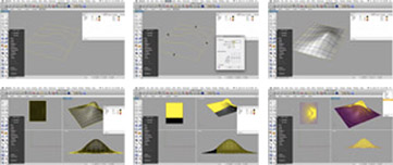
screenshots
of modeling process // in rhino: draw lines to create curve network;
use history command to remember actions using history allows one to
edit the curves, and the surface will re-adjust. create contour lines
in X + Y directions (command: contour), specify distance.
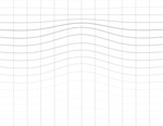

These two images are the resultant topographical lines in the x/y and the z for the bulge above, created to test scoring variances using the 3D settings in fablab. [reminder, white=bright=power]. Unfortunately, ran out of time. Hopefully will be able to sign up for some LC time this week and test this.