contact // irina chernyakova
1
[0912]
FINAL
PROJECT PROPOSAL
2
[0919]
COMPUTER
CONTROLLED CUTTING
3
[0926] ELECTRONICS
PRODUCTION
4
[1003]
COMPUTER
CONTROLLED MACHINING
5
[1010]
FINAL
PROJECT UPDATE
6
[1017]
MOLDING
/ CASTING / COMPOSITES
7
[1024]
EMBEDDED
PROGRAMMING
8
[1031]
3D
SCANNING + PRINTING
9
[1107]
INPUT
DEVICES 10[1114]
INTERFACE
+ APPLICATION PROGRAMMING 11[1121]
OUTPUT
DEVICES 12[1128]
MECHANICAL
+ MACHINE DESIGN 13[1205]
NETWORKING
+ COMMUNICATIONS 14[1212]
FINAL
PROJECT DEVELOPMENT 15[1219]
FINAL
PRESENTATIONS
1 printing
This
week, we're using the 3D printer and 3D scanner. Neil explained all
the various 3D printers in class, and I was fascinated by the recent
proliferation of 3D printing kits. Companies like Makerbot are
reducing the cost of a 3D printer to several thousand dollars.
Unfortunately, I was not able to prepare a file in time to print on
the ABS printer, which is a high-resolution printer that allows
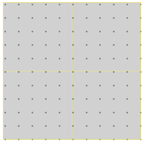
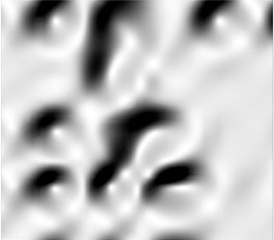
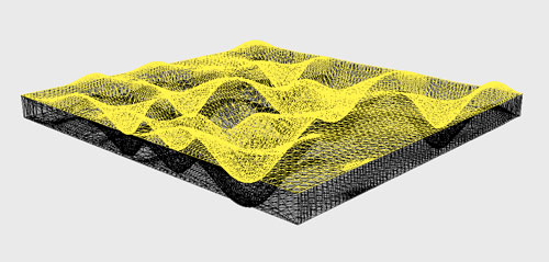
material to taper to ~1 mm. I prepared this file for the Zcorp
printer, in which I started to use the Paneling Tools plug-in for
Rhino. I used last week's QR code to manipulate a basic grid by
heightfield, then extruded the surface. The depressions are the
result of greyscale tone differentiation.
Notes
for preparing files: When
the object is ready to print, use the Show
Edges
command, and select Naked
Edges.
This tool will highlight naked edges in pink, meaning that two edges
are not actually connected. Use either the Join
command, or Boolean
Union
command to connect various edges/faces. Once there are no more
highlighted edges, export
as an .STL.
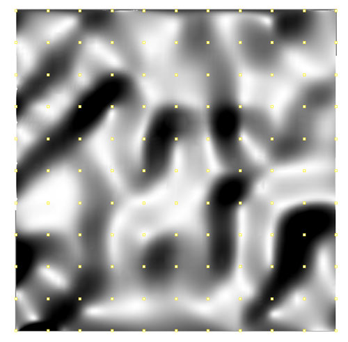
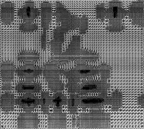
An .STL,
or stereolithography file,
creates a Mesh. You can open this file in Rhino, but won't be able to
edit. Use 3DS Max or a program like MeshLab to edit mesh objects. The
image below is the top view of the surface.
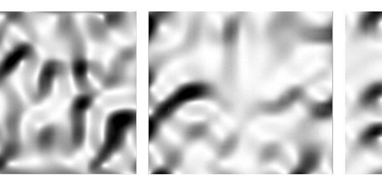
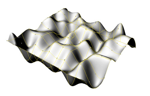
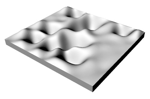
render
/ stl
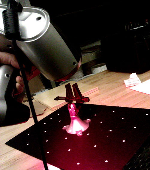
2 scanning
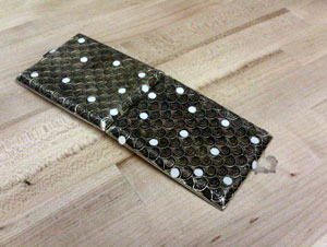
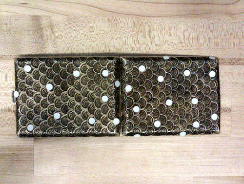
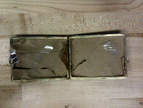
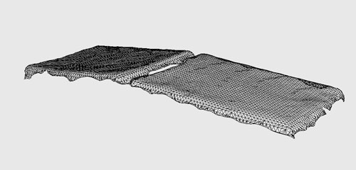
Scanning was simpler than expected. The alien kit-of-parts is packaged in an equally suspicious black suitcase. The process is relatively simple, and outlined below. I tried to scan my metal wallet, which is actually a cigarette-holder. It has a scalloped pattern, and almost lace-like detail within each scallop. I did not expect the scanner to be able to detect the actual pattern, but thought I would see how much it would capture. As visible below, the detail is completely lost by the scanner – it is best use for more simple curves and objects. I think the shine of the metal may also have reduced the quality of the scan.
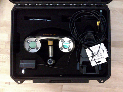
1
/ object
instructions:
1/
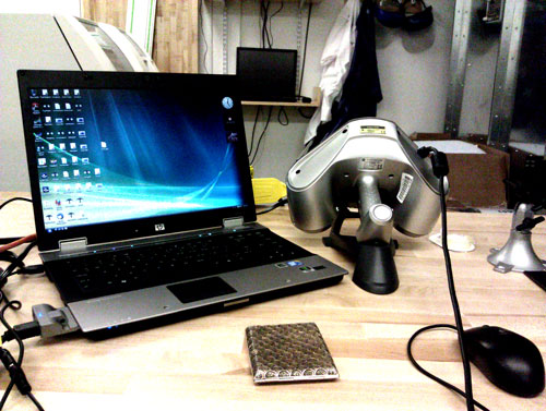
Set-up the the scanner. Plug in the computer, plug in the
scanner into the computer, then turn on the computer and open the
Zcorp scanning software.
2/ Configure the scanner. Open
the wooden box, and first Configure. The Y-axis should reach
as close to the top of the bar as possible, while the X axis should
be within the middle brackets. Auto-adjust to match the size,
and then Apply. Then in the same column of options, Calibrate
the scanner. While holding down the button and pointing the laser at
the white X, move it closer and farther away. The program runs
several iterations and calibrates the scanner for each use. This
should be done every time.
3/ Place the positioning dots onto
your object. They should be approximately 20mm – 50 mm apart
from one another, and not symmetrically placed. Intense curves should
have less positioning dots.
4/ Scan the positioning dots.
If these are places on your object, the scanner detects all of the
dots in order to produce a coordination system. It seems to then know
the location of each dot based on its location, and neighboring
relationships.You can find this in the top toolbar, Scan >
Positioning Dots. Press Record, and start scanning.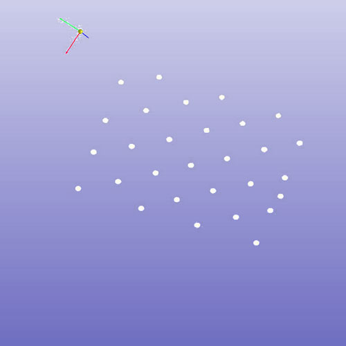
5
/ Once all of the dots are scanned, you can proceed to scanning the
object. You can find this in the top toolbar as well, Scan >
Surface. Watch for the crosshairs, and move slowly. You can watch
the file gather material on the computer screen as you move the
scanner around the object!
6 / One you've scanned, you can Stop
Recording. From there, you can adjust the resolution, re-size the
bounding box, or, if you're satisfied, save the file as an
.STL.
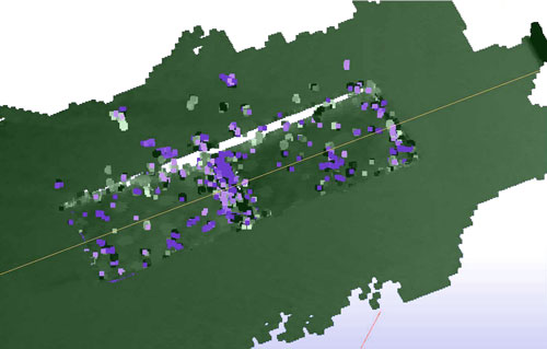
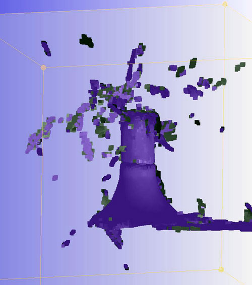
Results & Notes on
Scanning:
The metal object was too detailed. The scanner
understood the general shape, but did not catch any of the pattern.
The first time I scanned the laser seems to have moved through the
tiny holes in the material, and produced this explosion. 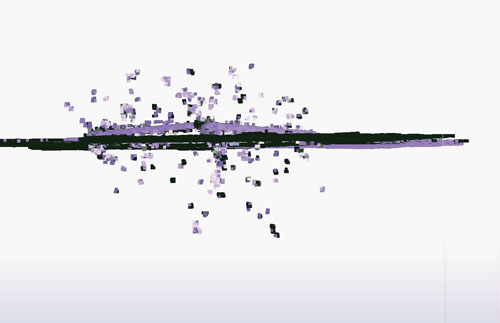
I
inserted a piece of brown paper into the interior to prevent this
from happening. Still not a great scan, much less chaos this time.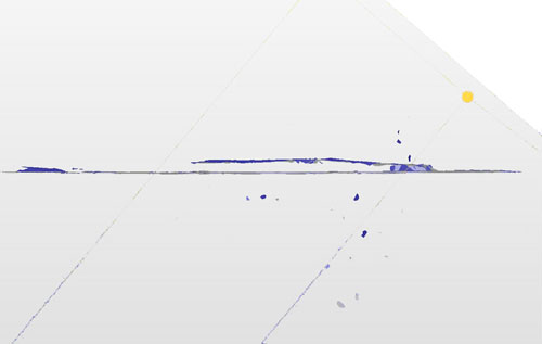
.
STL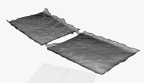
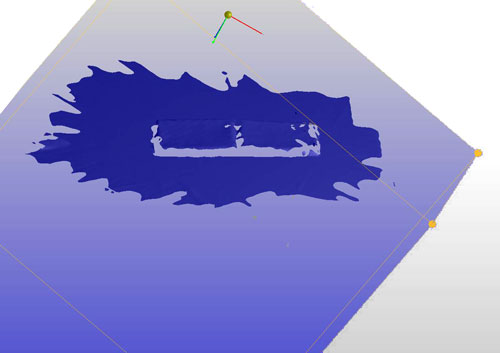
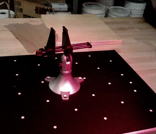
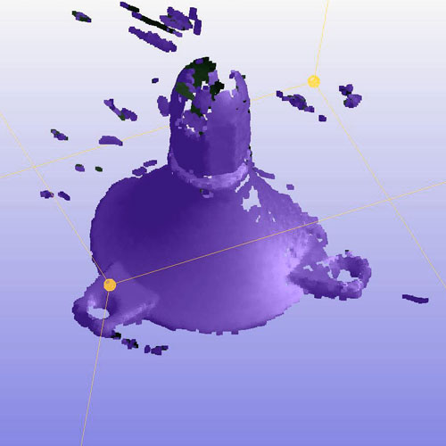
2
/ object on field
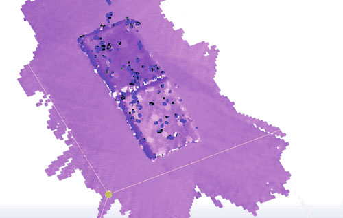
Since
the other object was too shiny and too detailed, I attempted to scan
this vice from the shop. In this case, I used the flat positioning
plane, and placed the object onto it. When using this method, you
can't move the object at all, or the scanner will get confused! You
can rotate the whole board, or move yourself – but not the object.
The bottom surface scan relatively well, as you can see below. I
don't the scanner was able to detect the top, black portions against
the black foamcore. Next time, remember contrast,
matte, simple. Since I
did not plan on printing these objects, I skipped post-processing and
tried out the milk scanner ..
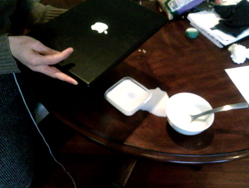
3 milk scanner
I
looked at Hannah's
page from last year for all of the information for milk-scanning,
downloaded the Milkscan
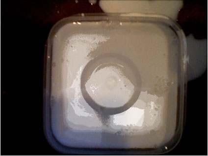
Software, and tried to scan a small bowl. The milkscanner
captures silhouettes of an object as it is being submerged into a
high-contrast liquid – milk for dark objects, soda for light
objects. I used a white bowl and a clear tupperware container, and
placed a small steel bowl in the center. Unfortunately, I don't have
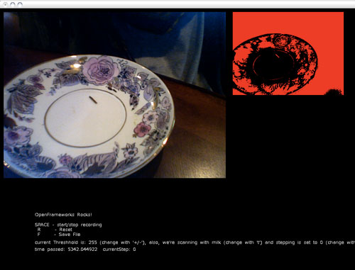
a webcam, so a slightly-rigged 90 degree computer had to do. The
software is supposed to capture single sectional slices and then
compile them into a single greyscale image that can be interpreted as
3D data in a Mesh-friendly program. I did not have time to process
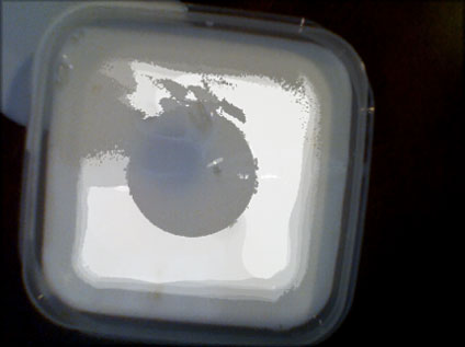
the data, but using the program was interesting in itself. Given the
rigged-computer and moving milk, the results were not very precise. A
more precise scanning method would be to take single exact
photographs, then using a image compiling program to produce a 3D
object.