Week 13
Final Project
The PowerSuit is a micro-energy harnessing shirt that functions based on temperature differentials between a persons skin and the outside environment. I am thinking of the skin as an activated landscape that can be used for micro-power generation.
The idea is to consider small increments of energy as useful towards a specific purpose such as lighting safety LED's while running at night time on cold days.
Fundamentally, this is a shift in how peope consider energy. Rather than constantly striving for tools and devices that are more powerful and less energy efficient, why not consider using small amounts of energy not typically utilized, and put towards more efficient devices such as LED lighting.
Please see image captions for further detailed information about materials, research, assembly.
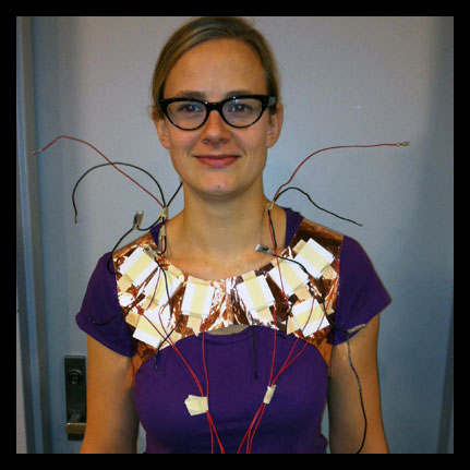
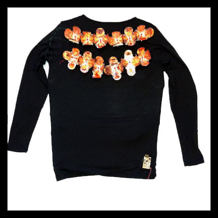 PowerSuit with custom heat sinks and circuit on display.
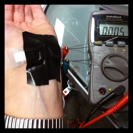 Early testing of miniature peltier devices to determine output.
 Testing small peltiers on a snap bracelet, the idea being use the tight fitting metal armature and surface area of the bracelet as a thermal enhancement to the system. Originally the design was to be for a bracelet that would illuminate based on the comparison of body temperature to environmental temperature.
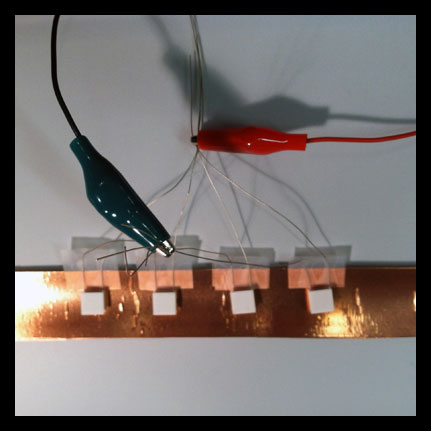 Wiring in series and parallel to test.
 Taking measurements with different wiring and in different temperature conditions, discovering that larger peltiers would be a better choice.
 Learing that larger peltiers would be necessary to create enough power - at this point the design shifted from a bracelet at a smaller scale, to thinking about a larger body covering mechanism.
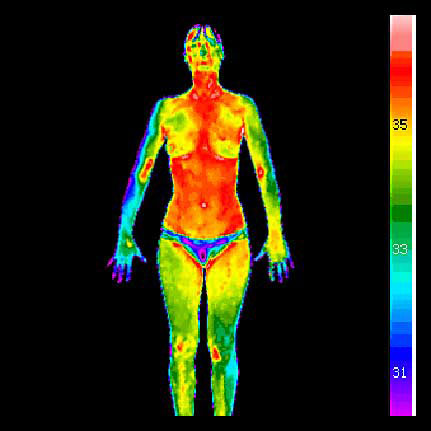 Consideration and beginnings of PowerSuit design. Looking at thermal imaging to determine warm parts of the body for best results.
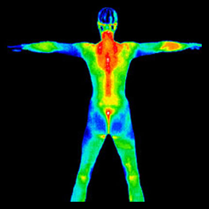
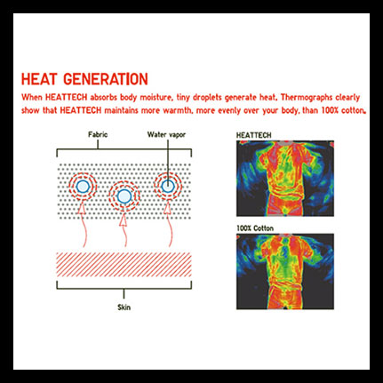 Considerations for materials - I decided to use Heattech fabric to enhance the thermal properties of the peltiers. I also investigated numerous types of materials and ordered samples of conductive fabrics, copper mesh, Dupont polymide films.
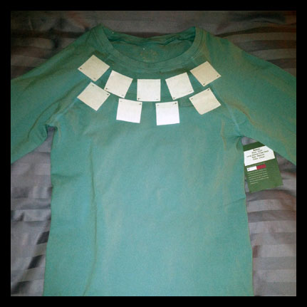 Laying out peltiers on the front and back to determine best placement according to thermal imaging and body structure.
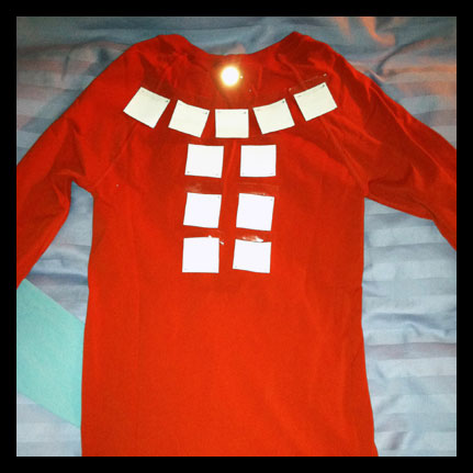
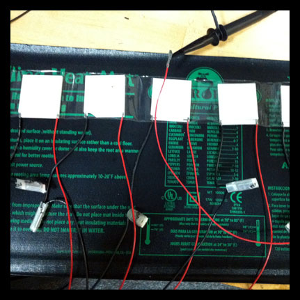 Testing the larger peltiers on heat mat to get more steady output readings.
 I began considering ways to increase power output and decided to create custom heat sinks for my application. Cutting out the bases on the waterjet.
 Putting together custom heat sink with copper woven pieces.
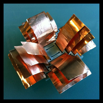 The aluminum is cut on the water jet, and the copper on the vinyl cutter. Each peice is woven through. The heatsinks at least doubled the energy ouput of the peltiers.
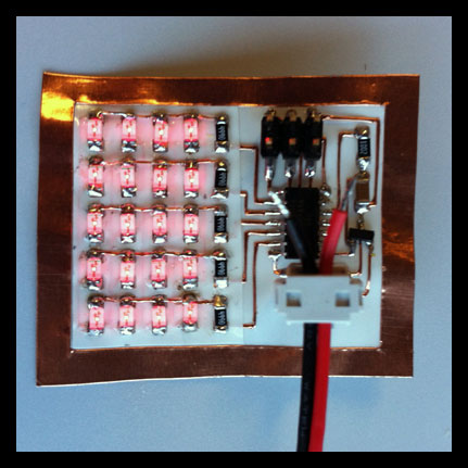
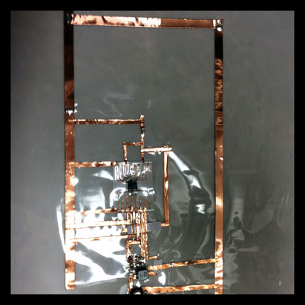 Much consideration went into the research and design of the circuit for the PowerSuit. I found a remarkeable boost chip that allows to boost microvolts to a useable output for LED lighting. Using conductive copper tape to begin laying out circuit and testing.
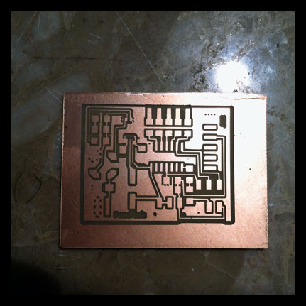 This is the first draft of the board.
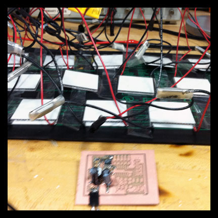 Testing the workings of the boost chip - it was working to boost 300 mV to 2.35V and above.
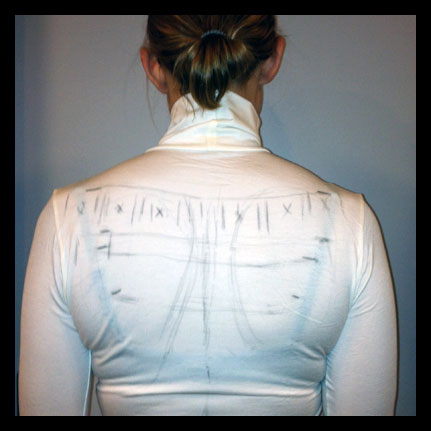 Moving on to the fabrication of the garment and placement of devices... Using Heattech fabric that helps retain more heat from the body at the surface of the peltier.
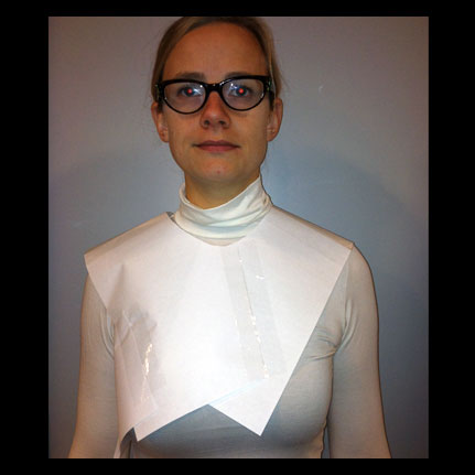 Making custom fit layouts for suit (this one is testing from folding paper), the idea was to create a close fitting copper sheath that the peltiers and fabric attach to.
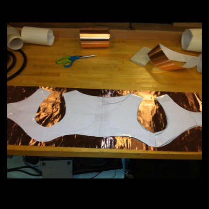 Laminating copper sheets and cutting out pattern.
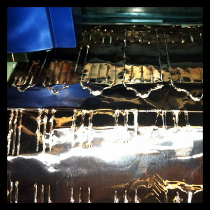 I also began laminating copper and cutting the woven parts for the heatsinks. This took a lot of experimenting since the vinyl cutter is very finicky, and I had hundreds of pieces to cut.
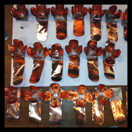 Here is the assembly line of the copper/aluminum heat sinks...There are 20 total for each of the 20 peltier devices.
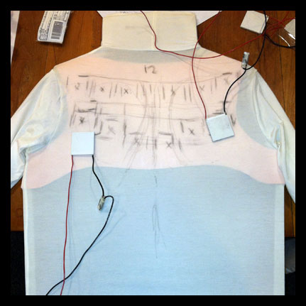 I created a model to build the components on... Here the copper sheath is underneath the first layer of Heattech fabric. I am laying out placement of peltiers according to heatmap of body.
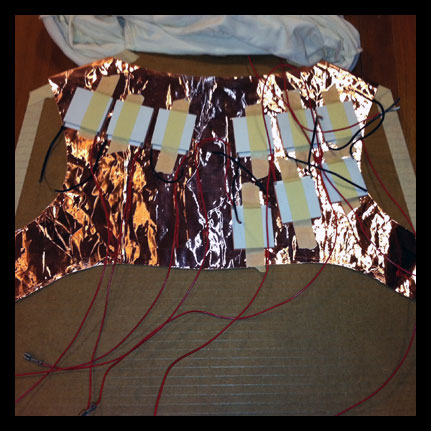 Placing peltiers on copper sheath.
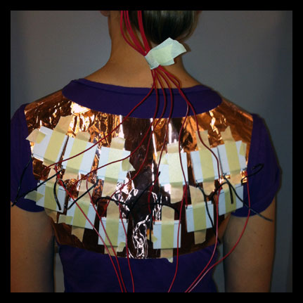 Wiring and layout on the back.
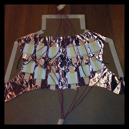
 Wiring and layout on the front.
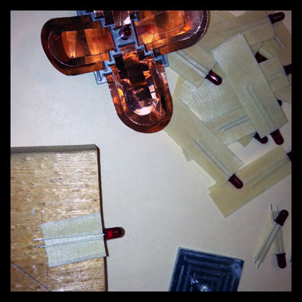 Using masking tape to remove conductivity between LED leads and copper/aluminum of heatsink. Each heatsink also doubles as a reflector for the special low current LED's.
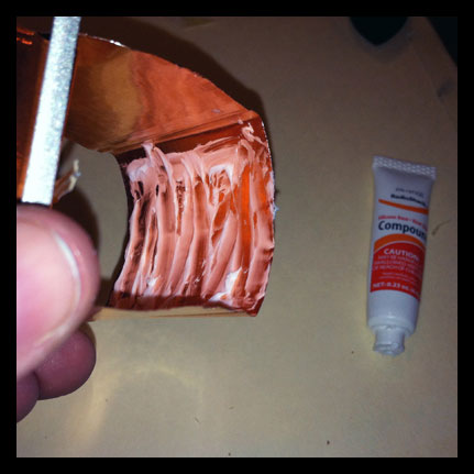 Once again, much research was done on improving the thermal qualities of the system - using thermal compound between layers of copper. I also used a special thermal tape to attach the peltiers to the copper sheath and to attach the heatsinks to the peltiers.
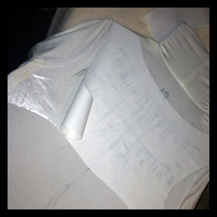 I also needed to consider the structural integrity of the system, since I am using a stretch material to get it as close as possible to the body. This elastic material makes it difficult to cut and maunt any kind of weight to. I used an iron on plastic to increase rigidity and to hold the fabric from unraveling when cut.
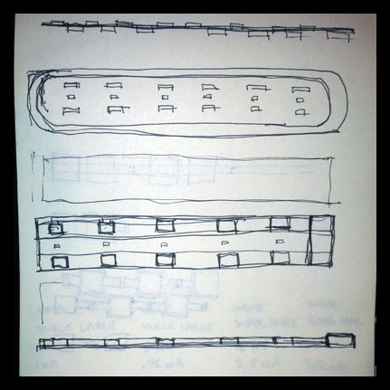
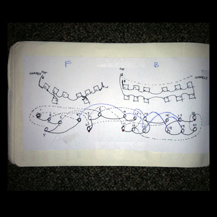 Here are some sketches of the peltier wiring layout, and also the charlieplexing layout and wiring to illuminate each of the heatsink flower LED's.
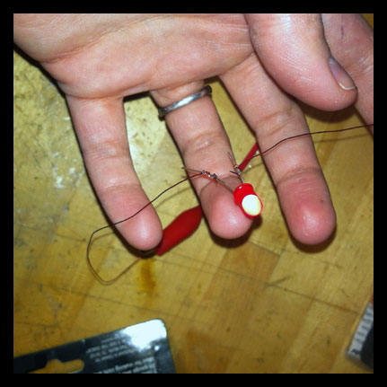 Testing lighting up LED's with proper power, and using thin copper magnet wire. I wanted to make sure that this wire would work properly - this is a much more lightweight and "thread-like" material for wiring the LED's.
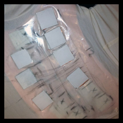 Cutting through the rubberized fabric to allow the peltiers the slip through. The idea is to create the most amount of heat on one surface of the peltier, and the coolest temperatures possible on the other.
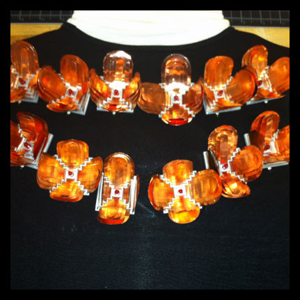 Placement of the heatsinks on the shirt, wiring to come...
Week 12
Networking and Communications, Final Project Update
I decided to try making the Hello_Radio boards to create my own radios. It turned out that there were a few hitches along the way that needed to be solved. I am currently having troubles debugging one of my boards - the other one is programmed and is functioning, but it does not have a friend to talk to!
On the second board, there was a short between ground and power. I desoldered and then resoldered each part on my board that was at all in proximity. I also used an exacto and carved out any areas that seemed problematic since the connections were very close to one another in the board design. After much time and energy, I finally found the area. I needed to replace some of the parts that did not make it through multiple solders.
I then tried to burn the bootloader and was still having issues. I checked the connections between the pins. There were some problematic lines after resoldering and I adjusted and reflowed the solder - but there is still an issue. I really tried to get this board working! Especially because the other one was in good order. I hope to have some help in troubleshooting.
I also spent much time researching, planning, consulting companies, seeking help within the lab, and ordering parts and testing for my final project. Thank you to Mark Feldmeier and Jie Qi for patiently answering and helping me with all of my questions!
I have now recieved most of the parts and have been testing on the new peltier devices I ordered. After finding searching and finding a fantastic boost converter for micropower applications, I feel confident that I can produce enough power to give a demonstration of the project. My hope is to prove the concept for future work and application. I am currently working on the circuit for the system. After testing a few different variations of "heat sinks" I discovered that the peltiers are 3+ times more effective. I am planning to design and fabricate custom heat sinks for my application.
I am still working to determine the form of the final project. Ideally, I would create the prototype as a pair of arm warmers, rather than a shirt (though I love the name PowerSuit!) - but this depends on how much of an output I can get from each device. I am very, very excited about this project!!!
 Fabricating custom heat sinks...more to come...
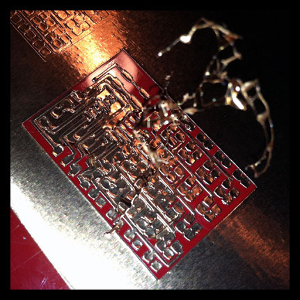
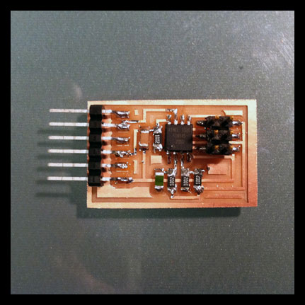
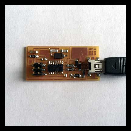
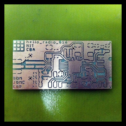 Boards after milling on the Modella.
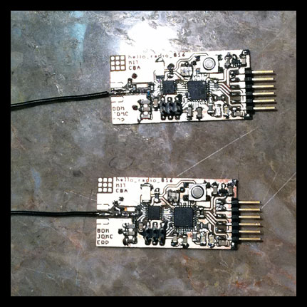 Stuffing the boards, later finding out that some of the components needed to be changed (keep 20 or 8 for the resonator, 10 MHz crystal with correct sizing).
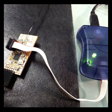 Board one worked well, once I discovered that P- command in fusebits needed to read "usb" rather than the actual port number. Also be sure that the downloaded files to program boards do not have the .txt default extension added.
 Bootloader and program uploaded to board.
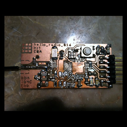 Now, board 2 had some issues... Ground and power were shorting. Going through all solders that were close between GND and 3.3V lines - removing and resoldering components. This was very tedious!
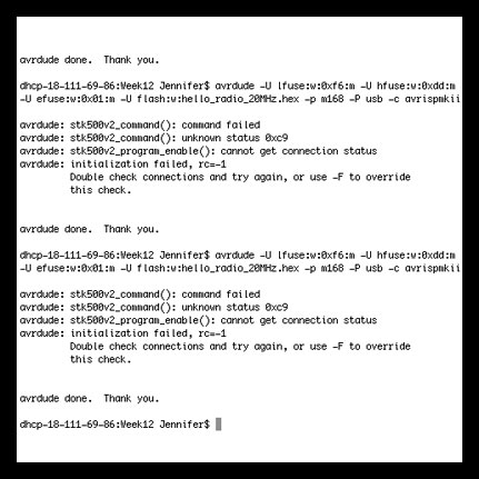 I am still getting errors! Even after fixing and debuggin pin issues. Very frustrating to have one board working perfectly and the other not functioning.
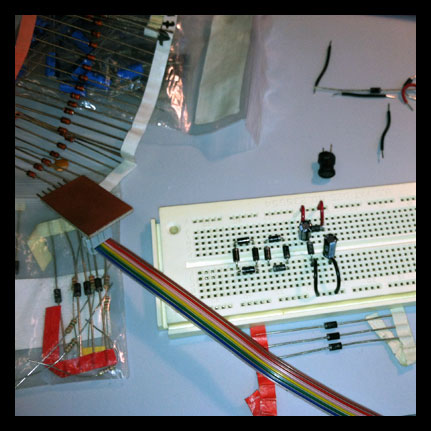 Researching and testing circuit layouts to boost voltage, rectify circuit.
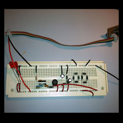 Trying AC ladder (both the rectifier and AC ladder were silly moves since the peltiers output DC!). Trying adjustable votage regulator. After researching and discussing with Mark - it seemed better to research DC/DC converters that do most of the legwork for you - and do it better.
 Looking at potential layouts for devices on front of shirt...
 Looking at potential layouts for devices on back of shirt...
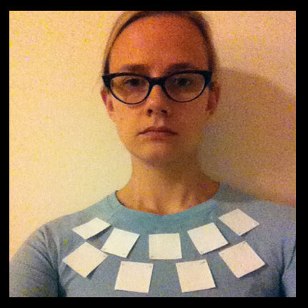 On the body - how do the devices move. How do they work on more elastic material?
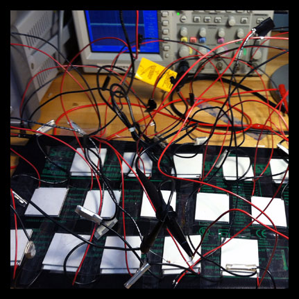
 Testing new peltiers - consulted with Tellurex regarding specs. These ouput very well for my purposes and I purchased surpluss parts. Testing on a heating pad for uniform and consistent heat check. 6 units wired in series.
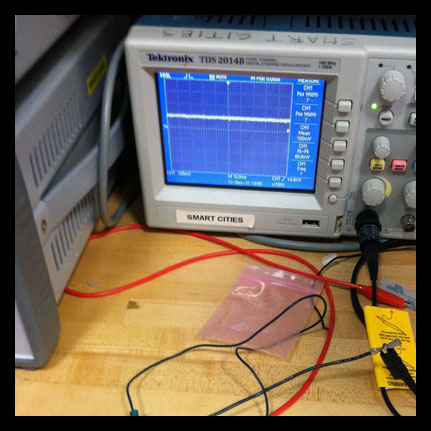 Readings on the oscilliscope are small, but they are enough to work with DC/DC booster chip.
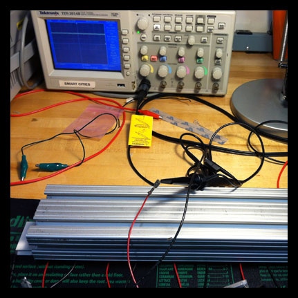 Adding a heat sink ups the ouput 3+ times. I plan to design and fabricate custom heat sinks for this project.
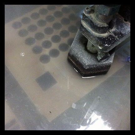 Cutting base for custom heat sink on the waterjet.
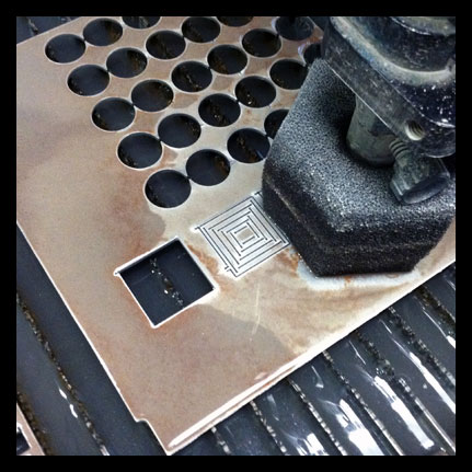 Continued cutting...
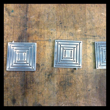 Slots cut to weave copper sheet through...
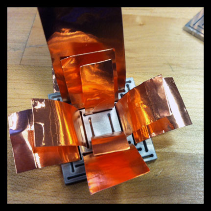 Weaving the laminated copper.
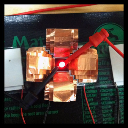 Adding LED to see how it reflects the light from the copper. The light here is not yet powered from the peltiers - I am still working on the circuit...
Week 11
Machine Design, Final Project Update
This week I focused on doing some testing and brainstorming for the final project. I also assisted with the assembly of the MTM Snap machine, and tried to troubleshoot the Fabduino again - making an entirely new board.
I am working on designing an energy harnessing device that works on temperature differentials between a persons skin and the outside environment. I am thinking of the skin as an activated landscape that can be used for micro-power generation. I have been consulting with a few different thermoelectric module companies to see how peltier devices can be used as generators rather than as power input to temperature change output. This has been an interesting and difficult task especially since I was trying to obtain tiny modules that could be used in a flexible array.
My testing this week has taught me many lessons. I want to create enough power to illuminate a small array of LED's. The purpose is to create a proof of concept prototype. The original design was to create a bracelet that could be worn, for instance by a runner at nightime in cooler temperatures, as a safety lighting device that would be powered by the heat generated from the body. I soon realized that the miniature modules (which I was most enthusiastic about) are not capable of providing enough output, even to light one LED. You can see my various tests on different parts of the body and with different size peltier modules. I also started testing with a multimeter, and then was advised to use an osciliscope (I still have a few tests to do in this area). I was testing with 8mm x 8 mm, 15mm x 15mm, and 40mm x 40mm modules. I consulted with some friends at the lab, who recommended using low current LED's.
At this point I realized that the concept and scale of my project needed to be revised if I wanted to continue in this direction. The larger peltier modules at 40mm x 40mm have the potential to work with a micropowered circuit and low current LED's. This has become a bit of a larger endeavor! I am pretty excited about it though!!! I started looking at some thermal imagery of full body scans to get some better ideas of where to place the peltier devices on the body to absorb the most amount of heat. I was finding that the upper chest and back are the most heated areas of the body and also the abdomen secondarily.
The new concept I have developed is for the PowerSuit.
What: The PowerSuit is a wearable micro energy harnessing platform that is applied to the landscape of the skin. The energy harnessed will be captured and directly applied to an array of LED's that will display the temperature of the user and act as a safety and thermal monitoring system. Example application: Running at nighttime in cool outdoor temperatures, lighting provided as a safety measure.
Prior Art: I have done a substantial amount of research and have not found any applications in this particular area. Generally, peltier devices are used to create temperature differentials (power in) rather than as generators (power out). They do, however, have the potential to be used in such a manner. There are a few applications of peltiers being used as self actuated sensor devices, and there is some buzz within the community of their potential to be used as generators. I have not found anything that uses them in a clothing/body application. I have found a research paper that looks at how to make a thinner/flexible version of peltiers - this is something that I plan to further explore once I have created a proof of concept with this prototype.
Needs: I have created a spreadsheet with items needed. I would like to review with the CBA team to receive further input.
Timeline: Week 1 - Ordering parts >> Circuit design and layout on CAD >> layout of pattern and placement in CAD/Rhino. Week 2 - Assembling parts (sewing, soldering, circuitry) >> Testing
Cost/Materials: I have put together an excell spreadsheet with further information.
 Sketches of concept for power harnessing bracelet.
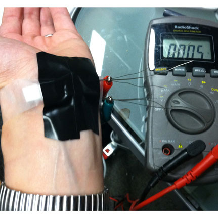 Testing output of midsize peltier device taped onto wrist.
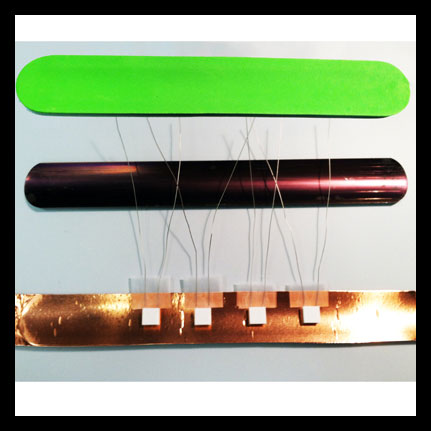 Using the metal from a snap bracelet (the idea being to conduct heat across the metal to the peltier device), laminating with copper tape and laying out the small peltier devices for testing.
 Wiring the bracelet in series and in parallel to test the output.
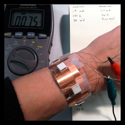 Testing the bracelet on my wrist with a multimeter. Seeing that the numbers were very small, I began testing the larger peltier devices.
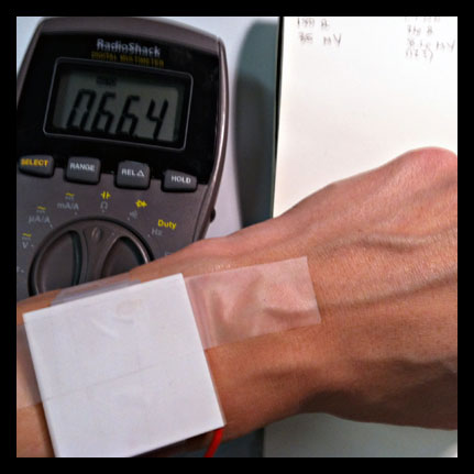 I also started testing on different parts of the body to see the difference in output with different delta T.
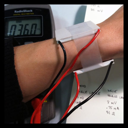 Testing two large peltiers in series on my wrist.
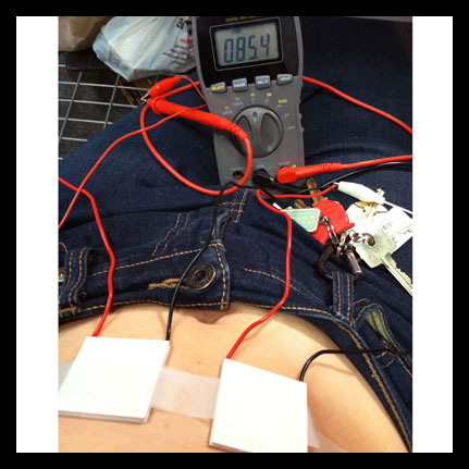 Testing two large peltiers in series on my abdomen.
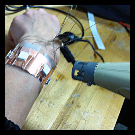 Testing the bracelet while blowing cool air on the modules.
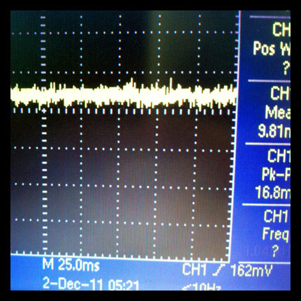 Testing the bracelet output on the oscilloscope.
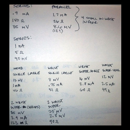 Log of output values for different sized modules, placed on different parts of the body and with different wiring.
 Thinking of the project in a different light...looking at thermal imaging scans of the body to determine best placement of peltiers.
 Front side thermal imaging.
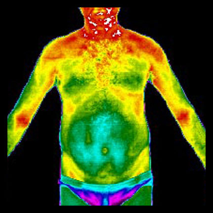 Front side thermal imaging.
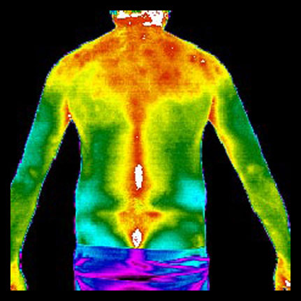 Back side thermal imaging.
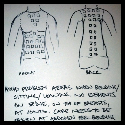 Sketch of beginning placement for PowerSuit concept.
 Idea of using Heattech material that seals in body heat for higher delta T.
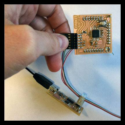 This week I also milled and stuffed a brand new Fabduino. It seems that the board is working, but I may have blown the USB port on my computer as it will no longer read my FabISP.
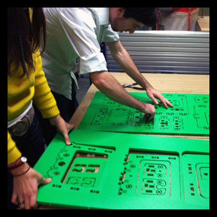 Assisting in putting together the MTM Snap machine. Filing the edges smooth.
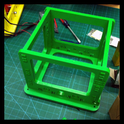 Assembling the structure.
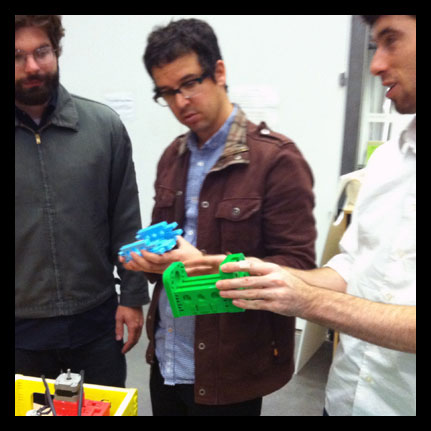 Discussing how the parts should be put together.
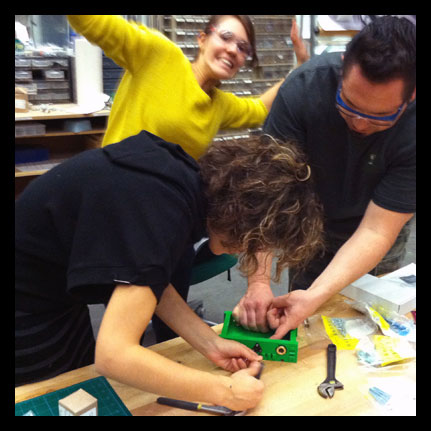 Assembly of the MTM Snap machine.
Week 10
Output Devices
This week I worked on trying to visualize my temperature sensor and potentially use both local data from my sensor and data from a larger network through Pachube, a realtime data infrastructure platform. Using both Arduino and Processing, Pachube/Pachuino connects through both to link local and remote data online. You can find further useful information about Pachuino here: Pachuino Though I did not get Pachuino up and running yet, I will continue to work on it.
I did, however, experiment with both Arduino and Processing to get a better understanding of how they worked. I realized that this step was necessary before I could understand how Pachuino works. So I did some tests with blinking lights through the arduino and contolling from the keyboard, blinking lights from Processing to the Arduino board. I also needed to readjust my temperature sensor to make sense out of the numbers I was getting. I tried to adjust the resistors to what was stated on the data sheet and was getting some really strange numbers. In the end, I used two 5K resistors (as I did not have a 10K through hole for the breadboard).
I was then finally able to understand and create a simple graphic output of my temperature sensor on the computer through Processing. Here is a great tutorial on the Arduino site that was of great help. I also was consulting a few books - Programming Interactivity and Arduino: A Quickstart Guide.
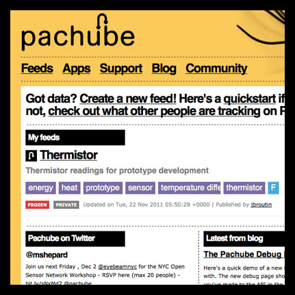 Setting up feed on Pachube for my local thermistor.
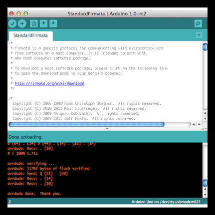 Setting up Firmata on the Arduino to run Pachuino.
- Realizing that I needed to understand Arduino and Processing a bit better, I set out to do some tests. This is blinking the LED through keyboard prompts with the Arduino.
- Getting the Arduino to blink an LED from Proecessing.
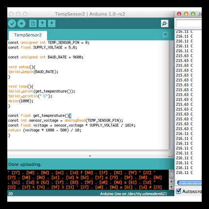 I also needed to adjust my temperature sensor to get numbers that were actually readable to humans. First trying to read from voltage, but realized that this particular thermistor does not read in this way (this code is also in Celcius)
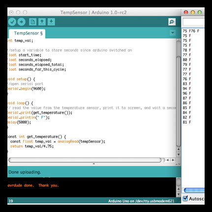 Looking at the data sheet for the thermistor, I adjusted the resistors and made an attempt for the equation. Getting some more accurate results.
- After these attempts I had a better understanding of how Processing works with Arduino, and found a great tutorial that helped me to create a simple graph of the output of my sensor.
Week 9
Output Devices
This week I wanted to experiment with flexible circuits and LED arrays. This is in consideration for my final project.
I used the vinyl cutter to make the circuits and went through some material explorations in order to get a circuit that was still flexible, but that did not melt during soldering. My original intent was to make the circuit transparent, but I soon learned that this is very difficult unless you have a heat resistant material (even if turning down the temp on the soldering iron, and being meticulous about it). Since I did not have an abundance of time to order clear heat resistant material, I may attempt this again in the future.
After numerous attempts (using the one layer layout on clear plastic sheet, layered circuit on clear plastic sheet, layered circuit on insulated tape), I finally settled for a thin layer of clear mylar, heat resistant tape, copper, and another layer of heat resistant tape for the via layer.
With the vinyl circuits, there is not a whole lot of forgiveness - if you solder something incorrectly it is difficult to fix since the pads just have a tendency to unstick. It is important to get it right the first time!
Now that I have a better understanding of the workflow/commands to program the board, the programming process went a whole lot smoother, though I did have a weak battery that lead to some confusion!
I got the LED running and it is pretty cool that it can take different shapes. This will be something that I continue to play with over the next weeks.
 Flexible LED array using charlieplexing and layered circuits in action!
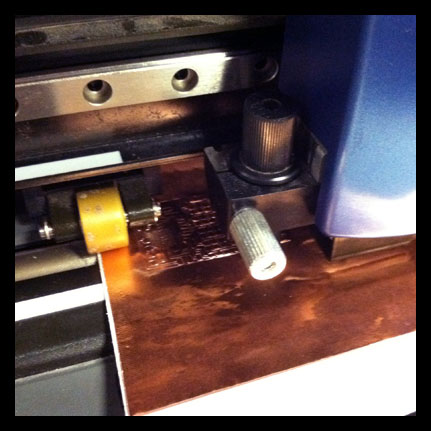 Using the vinyl cutter to print the circuits.
- Cutting on the vinyl cutter, love it!
 Carefully weeding the circuits afterward. This layout does not use the layered circuits.
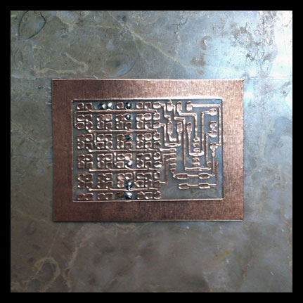 It was very difficult to solder without melting the plastic - even when lowering the temperature of the iron. I soon learned that when soldering to a plastic substrate, it is better to have less on the surface...
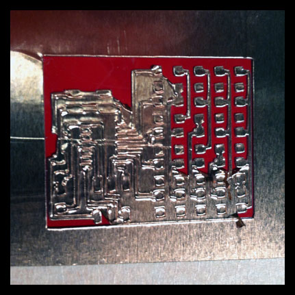 So I made the layered circuit which provided extra insulation with the via layer.
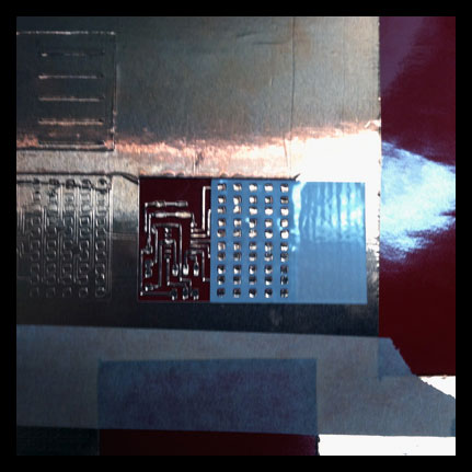 And I used the heat insulated tape.
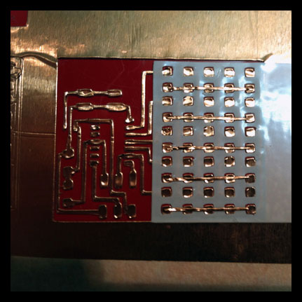 Added the top layer.
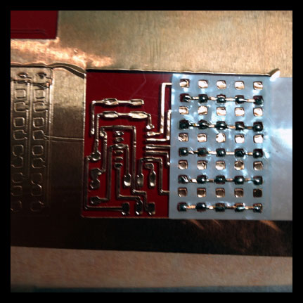 And soldered the top lines. I was still not happy with this circuit. As I continued to solder, the plastic continued to melt. So...
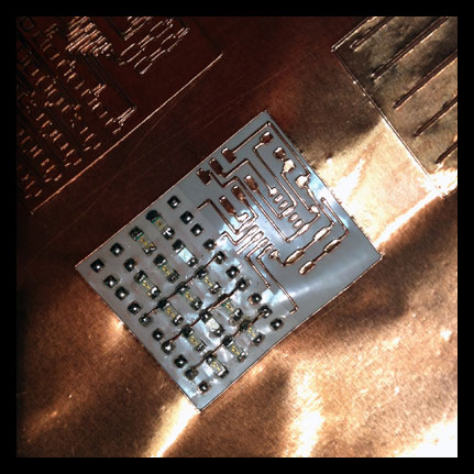 I made another circuit, with a layered substrate of thin clear mylar, heat resistant tape, then copper. The circuit was not clear as I originally intended, but it also did not melt!
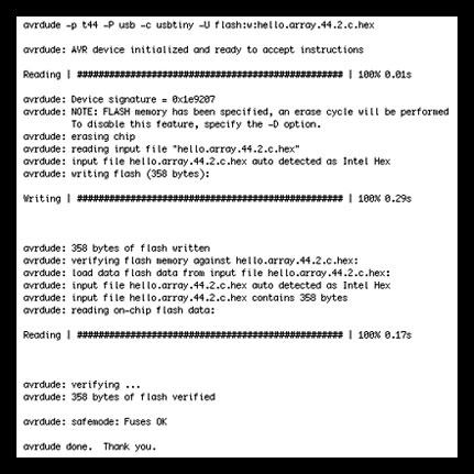 I hooked up my board which at first would not program (the battery did not have enough juice). Once I figured this out, I ran the make file and YAY!, it ran.
- LED Array in action.
Week 8
Input Devices
I first started by milling the boards. I milled the temp sensor board as a baseline this week, as this will be helpful toward a project that I am working on for urban farming. I also finished stuffing the Fabduino board and was hoping to get to hook up multiple sensors. This did not work out for this week, as I was still trying to debug my temperature sensor. I will continue to work on the Fabduino this week.
This week I had quite a bit of difficulty actually programming the sensor. This was largely due to the fact that I did not understand the workflow to program a sensor. Big thanks to Jennifer and Matt who helped me through this. For those who may have the same issue (and I think there were a few), I will run through the steps:
1. Program board through the FabISP and make sure all of your wires are connected properly to the pins. Also check the continuity of your board to make sure there are no poor solders.
2. Run the bootloader in Arduino to fuse the bits if needed (make sure you have the proper board, serial port and programmer selected).
3. Compilation: Run the makefile from terminal. This translates the source code (from C code or assembly code) into machine code (.hex file) and allows the board to understand the C code when uploading. For Mac OS X you will need to have Crosspack installed to compile C programs and Gavrasm installed to compile assembly code.
4. Upload: Run the C code from terminal or Arduino IDE. **It is necessary to run the makefile first otherwise the board will not understand the C code.** This step writes the machine code into the program/flash memory of the microcontroller.
5. Python code is used for visualization of the information received from the sensor only! Run the python code from terminal. Make sure that you input your serial port key (you can find this number in terminal by typing: ls /dev/tty.*). This should give you back something like dev/tty.usbserial-XXXXXXXX. Paste this into your python code (port = "/dev/tty.usbserial-A80016SY", for example).
This is a very useful CBA site for programming microcontrollers which I did not stumble across until later on.
I also wanted to practice programming for the arduino, so I continued with some work with the sensors and the arduino/breadboard. There is a video of some successful readings from a temperature sensor and photo sensor for a project I am working on.
 Temperature sensor board after milling and stuffing.
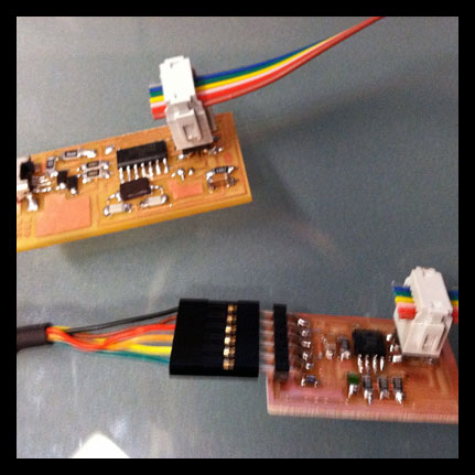 Connecting the FabISP and the temp sensor board to run bootloader and begin programming. Make sure all of your wires are connecting to the proper pins!!!
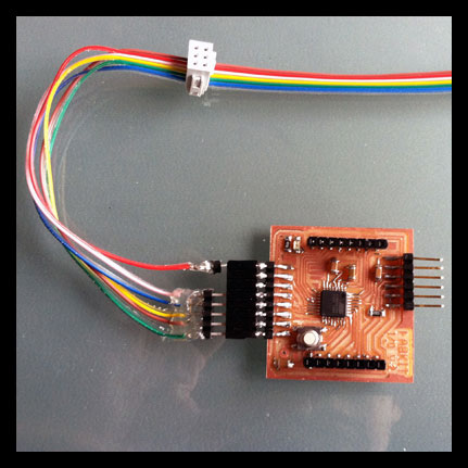 Finished stuffing the Fabduino board in preparation to connect multiple sensors (unfortunately did not get there this week!)
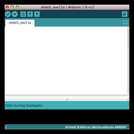 Bootloader went according to plan.
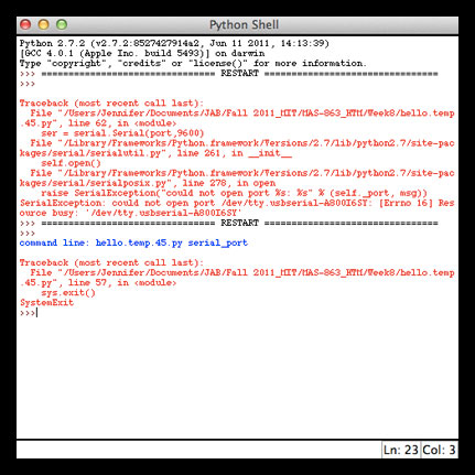 Then I started getting all kinds of error messages for multiple reasons, I tried running python program from IDLE on both Mac OS and on Windows. Also tried through terminal. Look at text for my debugging.
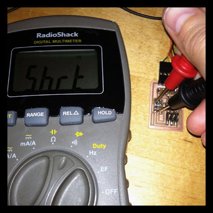 Tried to see if there were any issues with the soldering. Nope, everything worked well for continuity.
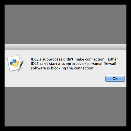 Other mysterious errors. Realized later that C code needed to programmed prior to running python script. Also needed to have PySerial installed and port number input into python code.
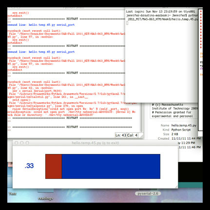 Strange thing was that it started to work, or at least brought up the monitor graph, but the circuit was still not programmed in the end.
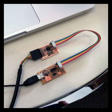 Trying again, with the help of Matt who explained the workflow.
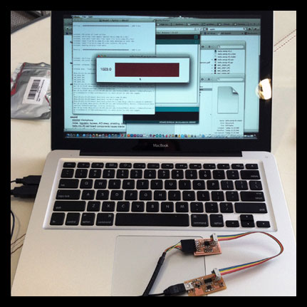 Hooray! Getting results!
- It is working! Though it seems like the sensor may need to be calibrated? Is it supposed to go down when heat is applied?
- I continued some work on the sensors with the Arduino IDE and board, running a temperature sensor and a light sensor.
Week 7
3D Scanning and Printing
This week I began developing/testing some ideas toward my final prototype. I am testing the possibility of harnessing small amounts of energy through peltier devices in direct contact with skin and the environment (Neil - I have to try this out to see if it will work!). The first images show the model that I created in rhino, a series of chained links that would each have a surface mount LED and tiny peltier device attached to the top and bottom of each link respectively. The model is misleading, since it seems like the parts are large, though each chain is 1.5 cm in diameter. The idea is to create a flexible substrate on which to mount the necessary components. These components could then either be cast in some sort of pliable material or could be embedded in fabric. Perhaps they work better alone, or perhaps they are not necessary at all - that is what this week's prototyping is testing.
The 3D printed model is super delicate! I realized after I tried removing a few pieces on my own (and then was told that was to be handled by John and Tom - my mistake) with an exacto-knife as per the online tutorial - that the links would continue to break using this method. In the end there were a couple of issues that we will try to resolve when printing again. First, when printing on the machine that does ABS plastic, the layers are not as accurate for doing small parts - it is better to use the machine with the acrylic. Second, something went a little strange with the mix of the materials for the acrylic machine on my batch - the substrate and final material mixed together and bonded. We are going to try to run the print again to see if this fixes it. UPDATE: Ran the print again at a larger scale, the model is more robust. Additionally once I took the parts home (both for the larger and smaller printed chains) and put in warm oil bath to remove the extra substrate, the links were MUCH cleaner. Now they are moving and flexible. I still will need to reconsider the design for the final project, but this is a good first pass.
The 3D scanning on the other hand was very tiring! I scanned multiple things multiple times with different parameters and with different colors/reflectivity. The scans that I was getting were poor at best! I understand the use of this process for scanning one of a kind pieces (like ancient artifacts), but to spend this much time scanning an object that I could model more quickly and more precisely in a modeling program made this whole process seem tedious and more of a headache than it was worth.
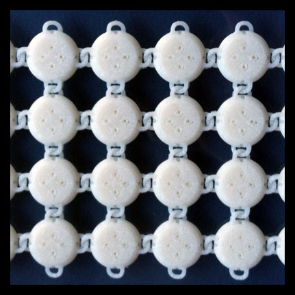 Finished 3D printed chain connections with ABS plastic. This machine is not as precise, so the chains fused together - will adjust in the model and use the acrylic printing machine instead.
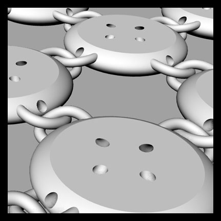 Model of links in Rhino. Holes are in place for running wires as needed to connect the LED's and the peltier devices.
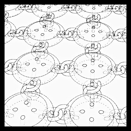 See through view of connections.
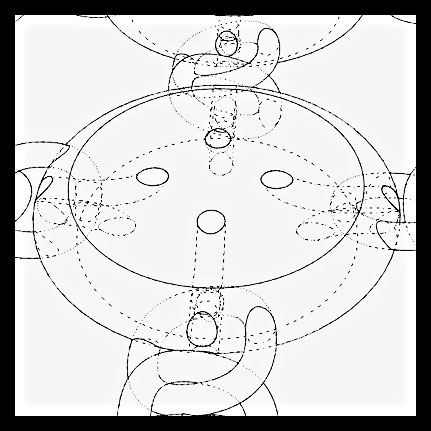 Up-close detail of link.
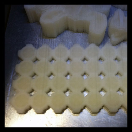 3D print after completed, it is encased in the substrate.
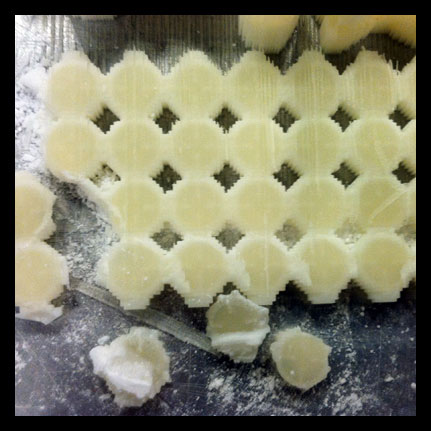 Trying to release the links on my own - bad idea!
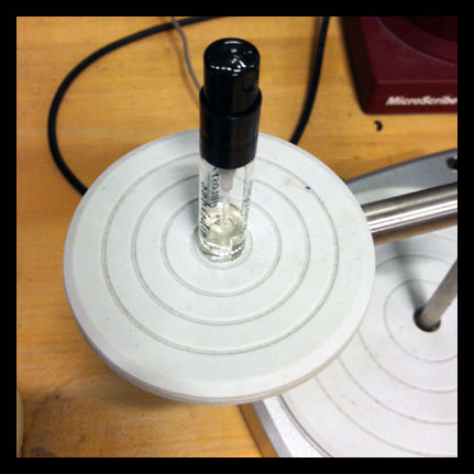 First I tried scanning a small perfume tester bottle (for a project I have been considering). No go!
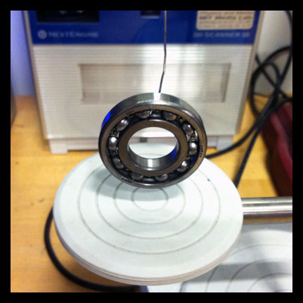 Then I tried a metal ball-bearing. No go!
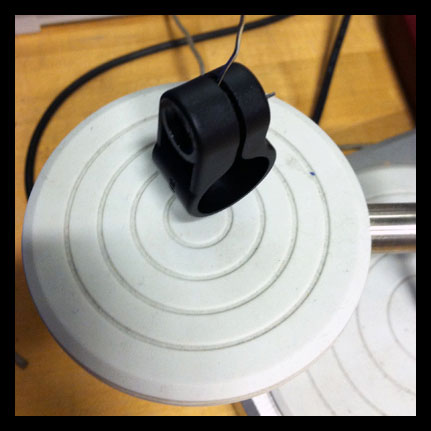 Then I tried a connector for a bike light. No go!
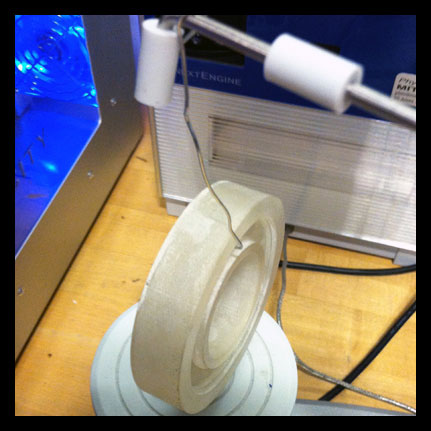 Then I tried the ball-bearing that was made on the 3D printer. No go!
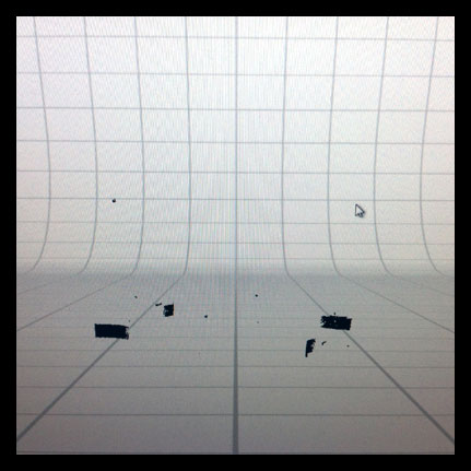 These are some of the results of the scans. Not very good.
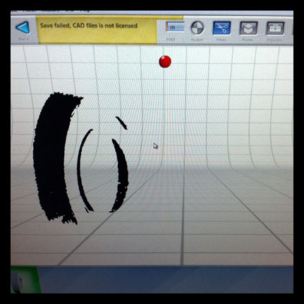 Missing many of the areas. The problem with this machine is that you really have no idea what you are going to get until it is done scanning.
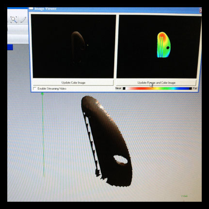 I then decided to try the Minolta, which seemed promising, but then I could not get it to scan the entire object no matter how many times I focused, moved the lens, moved the rig. This is a scan of a toothpaste tube squeezer.
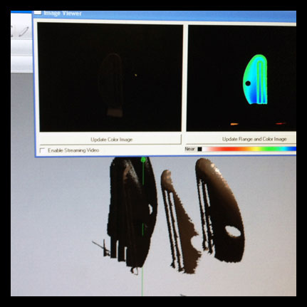 I also realized if it is not dead center on the rig, especially if you are working with a thin object - it will not stitch the pieces together properly.
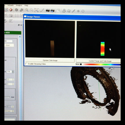 I then tried it again with the 3D printed ball bearing, the results were still awful.
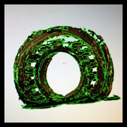 Lots of holes and inconsistencies! This process takes a lot of time, and I find that it does not do a fantastic job unless you tinker with it forever!
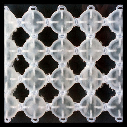 Checking on the 3D print once the substrate was removed. The acrylic machine is more accurate for the small links, unfortunately there was a strange mix with the substrate that bonded to the final material.
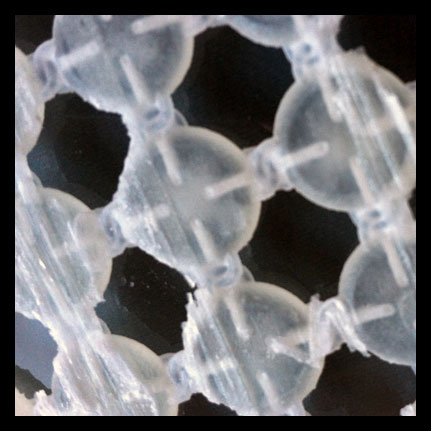 Up close image of the substrate bonding to the final model. I plan to reprint.
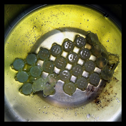 Warm oil bath to remove last bit of the substrate, this made a big difference for the delicate links of my chain.
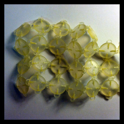 Larger chain links, they are now malleable.
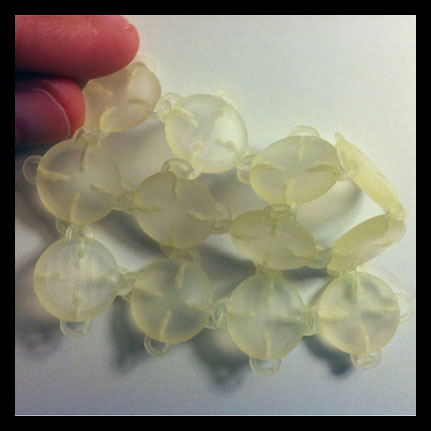 Smaller chain links are now moving as well.
Week 6
Embedded Programming
This week I worked on programming and making multiple boards as I wanted to get a general feeling for the different types I could work with. I also wanted to advance on a portion of a project for plant sensors that I am researching and included this towards this weeks' exploration.
The tutorial for Eagle CAD this week with Adam was super helpful, as this was the first time I have used Eagle with a clearer understanding - and found it much more useful than my past attempts! I created the .png for the ATtiny 44 with and LED and resistor with Eagle CAD.
Also thanks to David and Ed for great tutorials for the Arduino programming and ModKit. In total, I milled the hello.ftdi.44 board, the hello.arduino.168 board and also the Fabkit board. I have mostly soldered the components on the boards, though I have not programmed them all yet, but will continue working to do so. I do have my hello.ftdi.44 board blinking the LED. I had to troubleshoot the FabISP because it was not being recognized in my system information/usb panel. Once this was working and I connected my FabISP and hello.ftdi.44 board with the arduino tutorial from David - it was a fairly smooth process (minus a few hitches with the boot loader).
I also put together a kit called Botanicalls that I plan to hack for a project that I am working on. It is a smart little kit that monitors how much water your plants need and tweets the results to you. I have been working with some of the programming for ethernet and am continuing to work on that. So far I have the probes inserted into the soil of my plant and have it up and running to tweet. I would like to figure out a way to sense other aspects of plant needs such as sunlight, nutrients and also water for a hydroponic system. I also looked at David Robert's hello.plant example in a past HTM project.
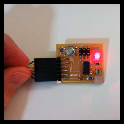 Final image of the hello.ftdi.44 board programmed with blinking LED.
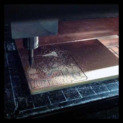 Cutting out boards (hello.ftdi.44, hello.arduino.168, Fabkit).
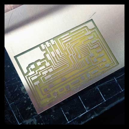 Milled hello.arduino.168 board.
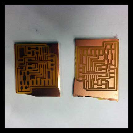 Using the cutting machine in the shop was leaving some nasty edges - needed to be sanded down on the belt sander.
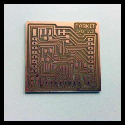 Milled and sanded/deburred Fabkit board.
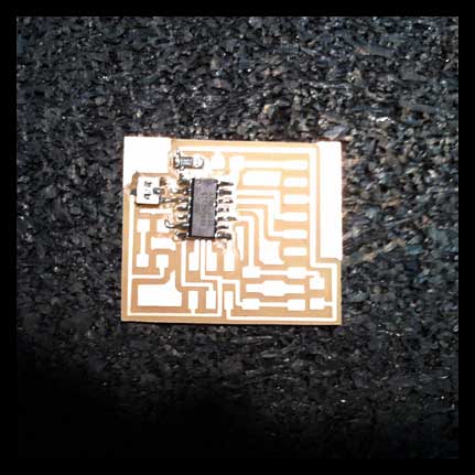 Soldering components onto boards - this one is the hello.ftdi.44.
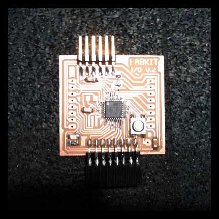 Soldering components onto boards - this one is the Fabkit.
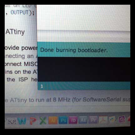 Hooking up the hello.ftdi.44 board with FabISP to Arduino IDE in order to program. Important to select under Tools > Board the ATtiny 44 WITHOUT 8MHz for now.
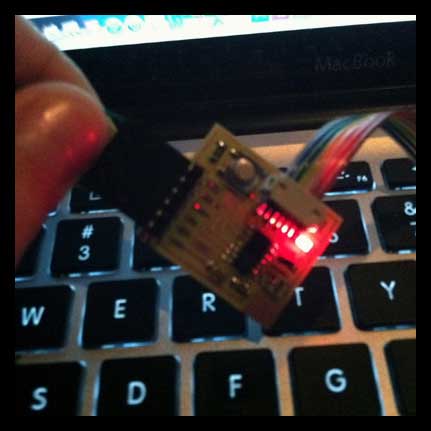 Running the program to the board… Yay!!! Blinking lights!
- Light blinking after running the program from the FabISP!!!
 I also began working on another project that looks at the Botanicalls kit for inspiration. Put together the kit and soldered all the components.
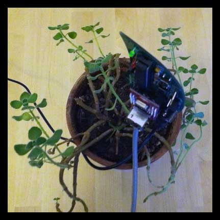 Inserting the metal rods in the soil to measure the water needed for the plant.
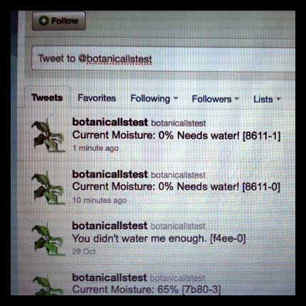 Testing to Botanicals Twitter testing site worked!
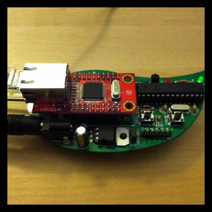
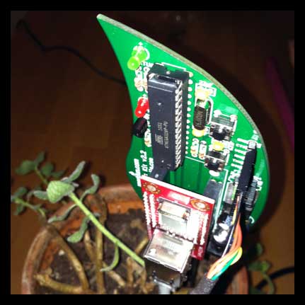 Removing the ethernet cord and inserting the FTDI cable to custom program the ethernet to new Twitter account.
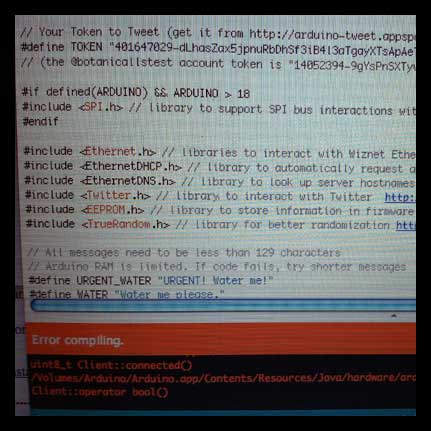 Getting some errors…still working on it!
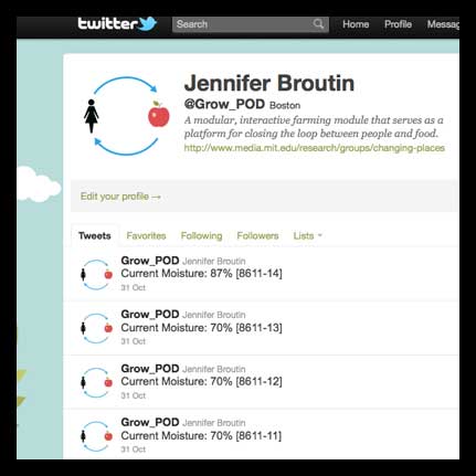 Continued working on it, now have it up and running on Twitter!
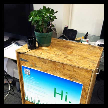 Hooked up for a demo on my Conversation Cart.
Week 5
Molding and Casting
This week I created my own version of the Yoshimoto Cube, which is a magic puzzle that has a myriad of folding sequences as you can see in the video. It was very difficult and time consuming to make because it is very precise! Ultimately I am happy with the results - though I do think that I would use a different material for making this project (I tried casting plastic, but also was not super happy with the results).
I used the Shopbot to create the first part of the mold from the milling wax - this was a fairly easy process, though it took much longer to mill than expected (or predicted by the program). In the end I had to stop the milling before the final cut, I only have the rough cut, because there were others waiting and it was taking too much time. In the end, I actually liked the patterning of the rough cut, and feel it adds a nice texture to the design. I then casted the blue silicon for the second part of the two part mold. This took longer than anticipated to dry, but worked beautifully in the end for the mold.
I casted many parts, since I knew that there would be some errors and wanted to make sure I had spares. I tried casting in both the HydraStone and in plastic which I dyed with a pink highlighter. Believe it or not the highlighter dye worked really well! Unfortunately the plastic by nature produces lots of bubbles! I may revisit this material at a later time.
Because I had to work with rough cut pieces that were not the exact size anticipated, I needed to do a lot of manual labor that should not have been necessary in terms of sanding. I would have tried to mill the piece again, but the shop was completely out of wax! Precision with this project is key!
One of the most difficult aspects was deciphering how the joints were to be made and the patterning which is very complex for this project. After testing with masking tape as a flexible hinge, I was finally able to create the hinge from a plastic coated paper.
 Final image of casted components, with flexible hinges attached.
- My version of the Yoshimoto Cube in action.
- Milling the wax on the Shopbot.
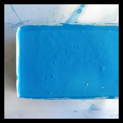 Casting the blue silicon into the first part of the milled wax mold.
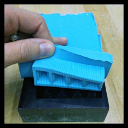 Releasing the silicon mold after it finished drying.
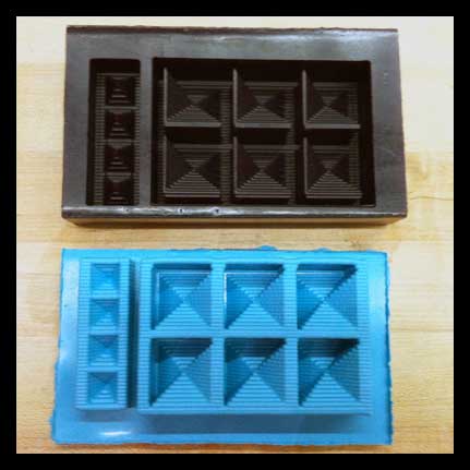 Two part mold.
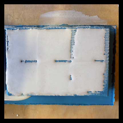 Casting the Hydro-Stone into the silicon mold.
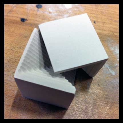 Components removed from mold and sanded smooth on the disc sander so that components fit together snugly.
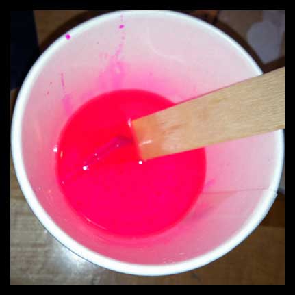 Mixing plastic with pink highlighter as a dye. It actually worked! I will revisit this technique.
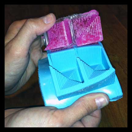 Removing plastic from silicon mold.
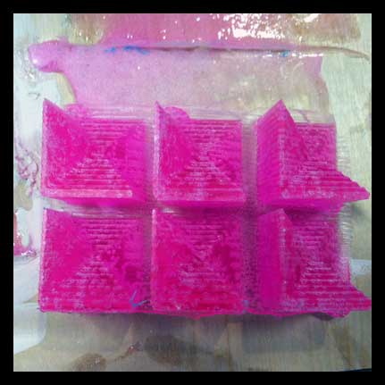 Plastic components.
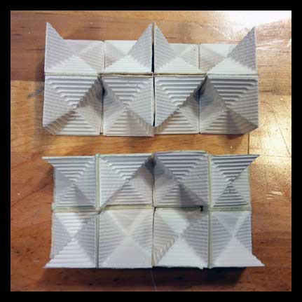 I decided to use the Hydro-Stone for the final product. I am trying to determine the pattern for the joints. This was very difficult to configure!
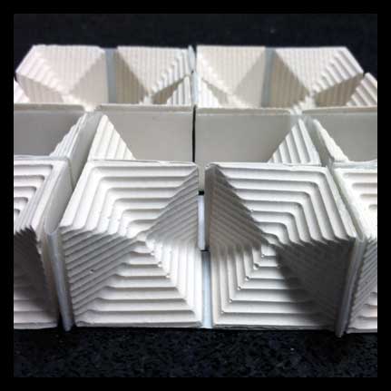
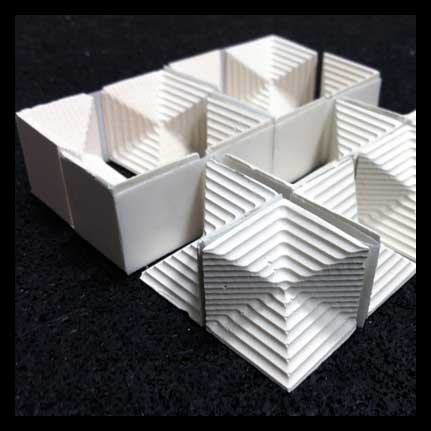 Final components all put together.
Week 4
Make Something Big
This week I used the Shopbot to create a rolling Conversation Cart. I used the cart during member week at the Media Lab to discuss ideas for my GrowPOD project. The idea was to engage people in a short conversation by offering them a tagged apple, then to discuss my "elevator" pitch with the boards attached to either side of the cart. If the person was interested in the project, I had my laptop available to discuss the project in more detail. I also created custom stools that would pull out of the cabinet of the cart for longer conversations. By moving around the Media Lab, I was able to talk to many different kinds of people - and I also gained many interesting perspectives and feedback on the project.
Thank you to those who donated their OSB to me for this project. I used three sheets of 4'x8' OSB and two 2'x8' insulated foam sheets to make this project. Also thank you to John and Tom for being extra patient and helpful!
The rolling cart was assembled using small 1/2"" dovetail joints. I used brackets on the interior of the cabinet to hold in place, but the cabinet itself did not require wood glue to stay together (I was avoiding using wood glue if possible). I used large ball bearing casters on the bottom to roll the cart around, and I also installed metal handles to push the cart and metal hinges to open the cabinet. I was experimenting with laminated foam and OSB for the seating. At first I was trying to make completely out of layers of OSB, but the seats started to become very heavy. Instead I decided to mix in layers of foam to lighten the stools - I also liked the play of materials. The cabinet was designed to hold the interlocked stools, as well as an extra shelf to hold more apples and business cards etc. Altogether, I feel it was a really successful project and I am proud of the results! I am planning to use the cart for my demos so that I can make them moveable as needed.
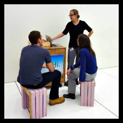 Discussing GrowPOD project with the Conversation Cart.
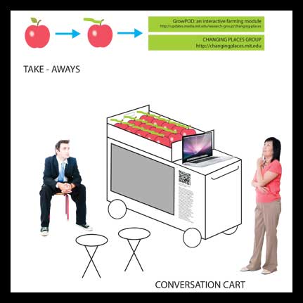 Concept diagram.
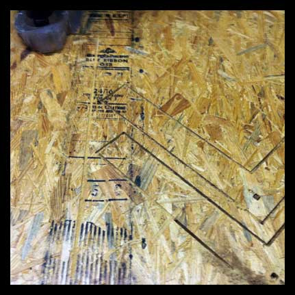 Cutting OSB on the Shopbot.
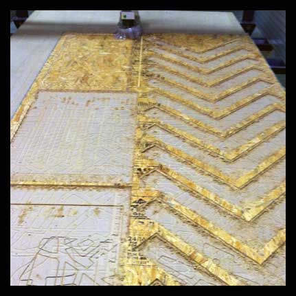 Cutting OSB panels for the cart and for the stools.
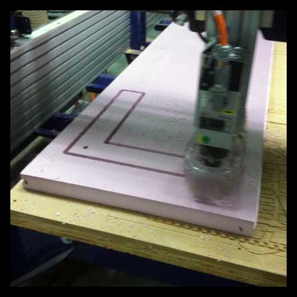 Cutting insulation foam to create laminated material for stools.
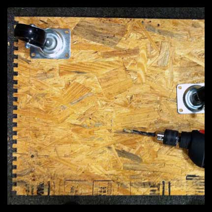 Assembling the cart - adding casters to the bottom for rolling.
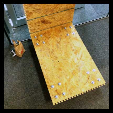 Assembling the panels of the cart.
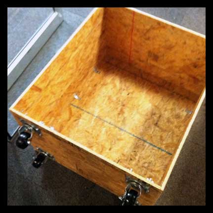 Using L-brackets to hold in place. I tried to avoid using wood glue.
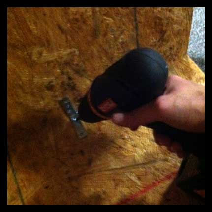 Installing L-brackets.
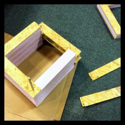 Assembling layered material for stools, using wood glue, with alternating layers of OSB and foam. An OSB dowel holds all of the pieces together.
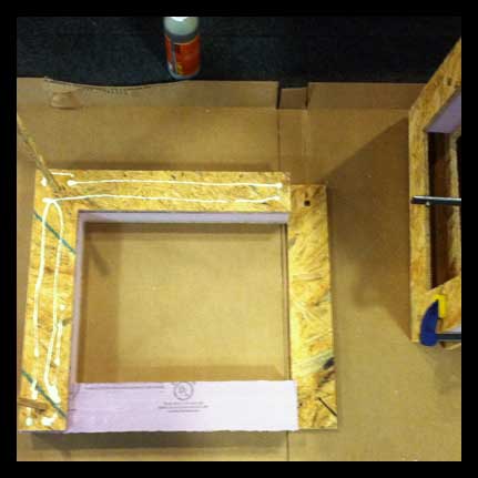 Gluing panels together for stools. Holding together with vice grips while drying.
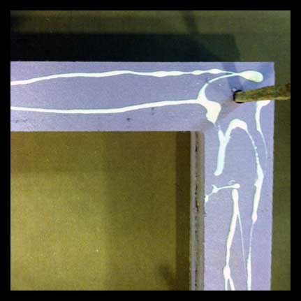 Detail of assembly.
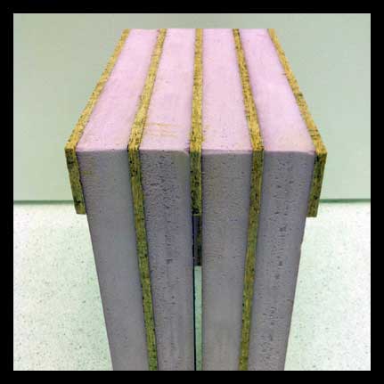 Finished stool, sanded and ready to be sat upon.
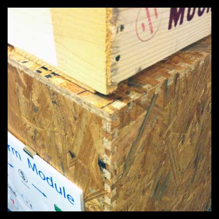 Detail of dovetail joint for cart.
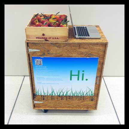
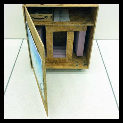 Stools concealed in cabinet.
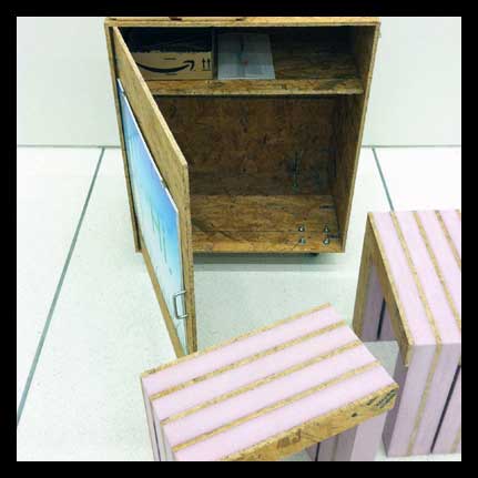
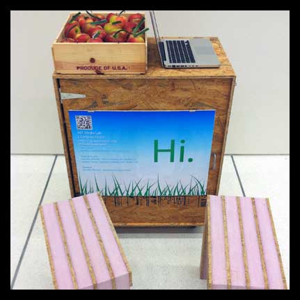
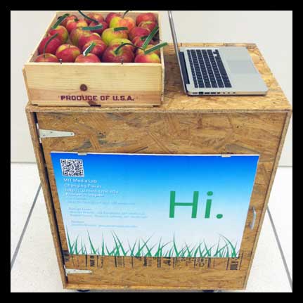
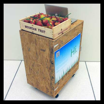
 Conversation cart out and about during member week activities at the Media Lab.
Week 3
Printed Circuit Board
This week I created a FabISP (in-system programmer) by milling a custom printed circuit board on the Modela machine. During this process, I learned that it was important to have a sharp end mill (blade) for the milling, otherwise you need to slow down the cutting so that you get smooth edges. The first board I milled came out with rough, uneven edges.
Next, I soldered the surface mount components for the kit. I have a good deal of experience soldering, but this is the first time I have ever tried to solder surface mount components - and boy are they tiny! I followed Neil's recommendations to start soldering components from the center of the circuit out (this is very helpful so that you do not have to maneuver around components). I also began by adding a little solder to one of the pads for each component and then laying the component on top, melting the solder and using this connection as a base to hold the component in place. This is very helpful!!! Another important point is to follow instructions for the solder jumpers - they must be jumped to program the board and then broken before hooking up to your computer.
I then connected the fabISP to the computer and downloaded the firmware.zip and CrossPack AVR - changing the makefile as noted here and then running the avrdude. One thing that I did not realize - silly me - was that the FabISP must run from another micro-controller to install, it can not be programmed without one (in other words avrdude is an actual physical piece of hardward, not just programming code). Jennifer gave me this helpful hint! After running the program I got a green light! Then I broke the connection between SJ1 and SJ2. I hooked up to my computer and the USB port under system information did not recognize the device. I checked all the solder joints for continuity, checked the resistance of the resistors, and re-soldered areas that I thought may need better connection.
 Finished PCB.
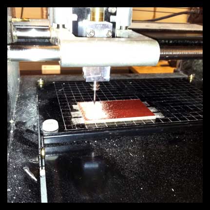 Cutting out material on the Modela.
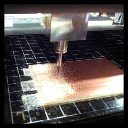 Up close to the milling.
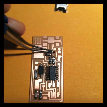 Soldering the surface mount components. They are tiny!
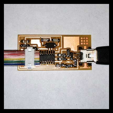 Getting PCB ready to attach to another FabISP for programming.
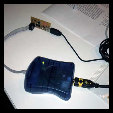 Green light when connected! Hooray!
Week 2
Press-fit Construction Kit
I was interested in making a beautiful and simple press fit construction kit for jewelry. I became fascinated with developing a flexible joint for the system, that became an integral part of the design. I also wanted to use the vinyl cutter exclusively since I have previous experience with the laser cutter, and because I wanted to cut thin sheets of metal which is not possible on the laser cutter.
To begin with, I was experimenting with floral patterns, and then realized after testing and making some simple models, that this was not the route I wanted to take. I began sketching a system to that was less tedious, and decided to implement. The final design incorporates components that are modular and scalable - the chaining together of the pieces gives the desired length for the user, and the different size components allows people to create their own pattern.
In order to get the desired rigidity for the joint to move smoothly - I experimented with different laminations of the thin copper on different backings. I finally determined that a thin layer of acetate sandwiched between two layers of copper was best.
Another material that I wanted to explore was using colored sheets of thin plastic, that when overlapped would produce a color-wheel effect. The joints and color transparencies would make the connections visually active.
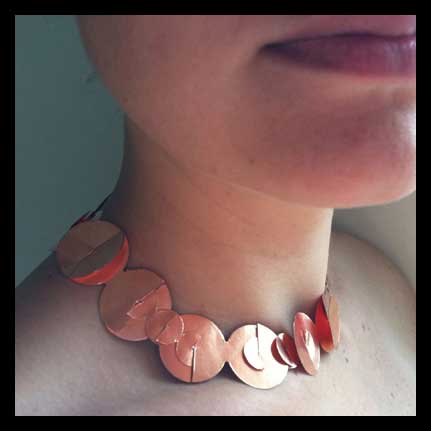 Finished copper necklace with moveable joints.
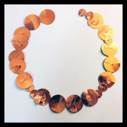 Small and large components interlock and move past one another to make flexible joint.
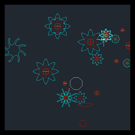 Early drawings for concept.
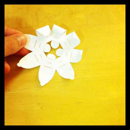 Early models out of paper.
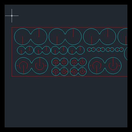 More developed CAD drawings for modular jewelry kit.
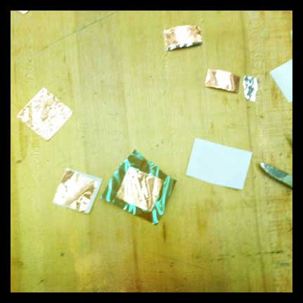 Testing materials, laminating layers of copper and acetate, also thin sheets of plastic to develop proper thickness and rigidity.
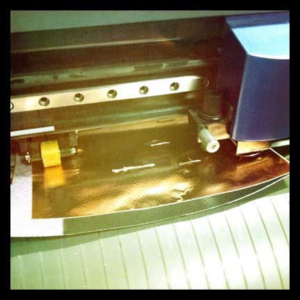 Cutting on the vinyl cutter.
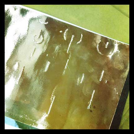 Cutting on the vinyl cutter - this particular material was too thick to cut.
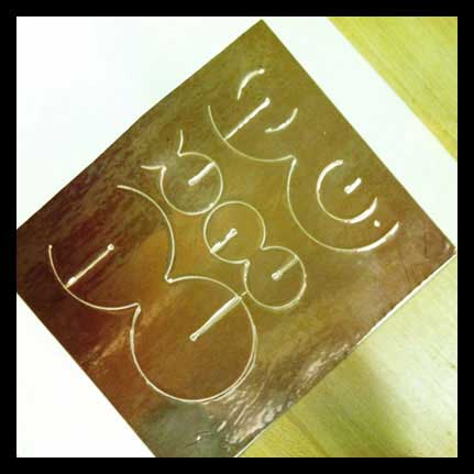 Cutting on vinyl cutter - copper on manila board. This cut through but I did not like the texture.
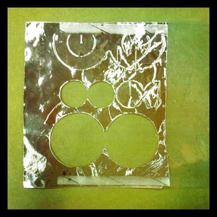 Cutting on vinyl cutter - two layers of copper sandwiched around layer of acetate. This had the best consistency and texture.
- Video showing movement of joints.
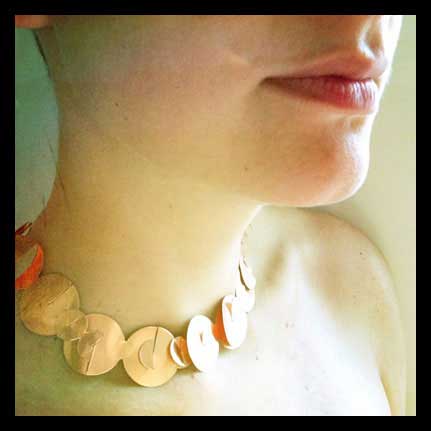 Final copper necklace.
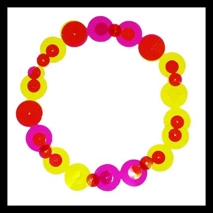 Necklace made of colored plastic sheets that make the joints more active through color patterning and transparency.
Week 1
Final Project Proposal
As a designer by training, I believe in conceptualizing and creating functional, useful and beautiful works. I am very interested in pursuing a final project that I have been excited to build for some time. The project is also complementary to my research within my lab group. I plan to build an installation using the energy from a (or multiple) custom made Stirling engines or thermogenerators, that would involve the different modes of fabrication learned in the class. A Stirling engine runs through temperature differentials between surfaces, otherwise known as the Seebeck Effect.
Two strategies that I am considering for the design and application of this custom system:
1. Capturing waste energy of city systems such as excess heat from the subway that could be transformed into cool air.
2. Application for micro scale stirling engine/thermogenerator - a fabric that could be worn on skin, creating energy through temperature differentials from the body and the environment.
Project Update
What is the goal?
The goal is to capture small amounts of underutilized energy and convert into useful energy that will accumulate over time.
What is the prior art?
There are a number of models built of sterling engines (and I am also researching thermogenerators/peltier effect), but the sterling engine assemblies are often used as diagrammatic displays the engine rather than being used toward a purposeful application. Thermogenerators are often used to cool off CPU's which is the largest application for the technology.
What are the systems and components?
The system will require input, processing and output. The input will be the initial heat (or cold) entered into the generator. I would like to design this for use in clothing applied to warm skin, so the input would need to be embedded in some kind of fabric that would not dissipate, rather accentuate, the thermal characteristics needed for the system to work. The processing portion would be the generator - and its design. I would like to break down the sterling engine/thermogenerator to develop a series of small scale generators. If possible, I will try to hack into existing devices to work as efficiently as possible. The output will be to cool (or inversely to heat) an area contrary to the initial input. I would also like this to emanate from the fabric which will be used as a conduit to transfer the cool air to parts of the body needed to be cooled.
What questions will you need to answer?
I will need to figure out whether this will work at a small scale - whether the effect will be great enough to make a difference. I will need to figure out a way to make this in a manner that is cost effective, and will need to hack into parts that are available. I have found some parts, but need to test how effective they will be.
 Capturing heat from subway and converting into cool air.
 Potential for creating a thermogenerator fabric that can be applied to warm skin that produces cooling effect.
 Original patent drawings for Stirling Engine.
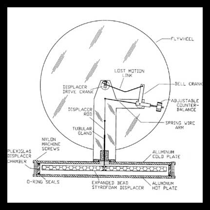 Version of Stirling engine that can be placed on your hand and create a fan through the slightest temperature differentials.
- Movie showing the motion of one type of Stirling engine.
- Using a thermal couple to create power from temperature differences between hot/cold water.
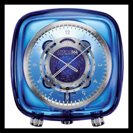 Atmos clock designed by Marc Newson for Jaeger-LeCoultre. Clock runs off of temperature differentials in the air. The important concept to note is that though it produces a very small amount of energy - the device is optimized to function with this small amount of energy. This is a conceptual change in the way that we think about energy use.