Dinosaur skeletons!
Yes, you remember, those balsa wood kits you could put together at home, and you could have wooden skeletal replicas of T-Rex and Brontosaurus facing off on the battlefield that was your dresser top.
Well, at the very least, I remembered them, and once this assignment went out, this was the first thing I could think of building. Designing a cardboard kit for a dinosaur would be perfect! Except, when I thought of it, the project sounded so unoriginal. However, it made for a good test run, so I decided to do that first.
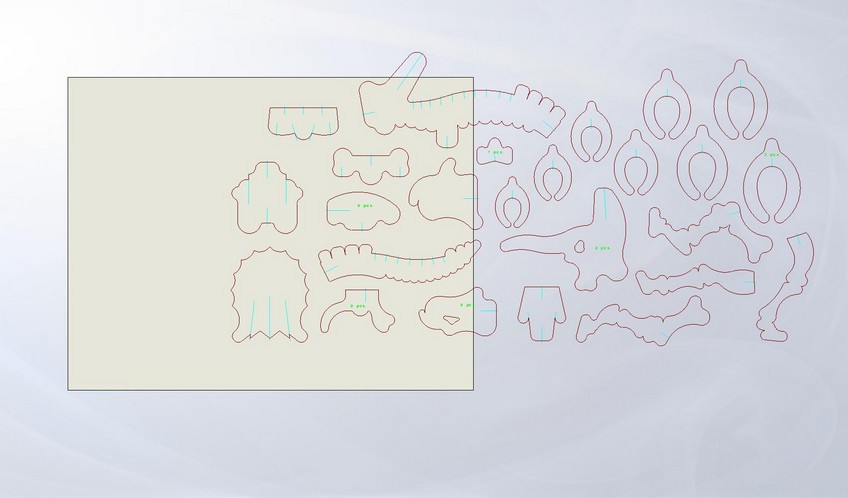
Rather than try to "draw" a dino skeleton in SolidWorks (my DXF program of choice), I did a bit of searching on the Internet for some pre-made DXFs (again, this was a test). I found this forum for milling called cnczone.com, and the user "ger21" provided this nice Triceratops skeleton shown below.
However, this was designed for the mill, and so I had to make the slots myself. Thankfully, the center lines were all there, so I knew where to make the slots, and how deep to make them. I noticed that the drawing was made for 0.25" press fits in birch, so I decided to scale down the drawing based on the press fit size I would use. With a bit of testing, and help from previous years, the fit I wanted was a 0.145" gap thickness. The cardboard itself was 0.166", but I knew that its compressive nature would require more than just a couple thousandths for a tight press fit.
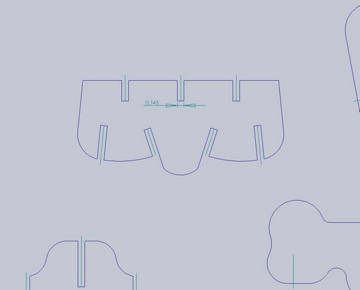
Once all of the slots were created as shown above, I used the "Sketch Fillet" feature to round the edges using a 0.05" radius fillet. (Chamfering does not work well with round sketch features it seems.) I then divided the entities into two pages for cutting. This was going to be one big dino.
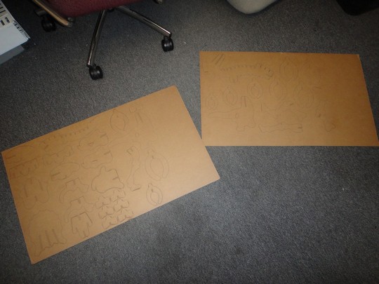
From testing, I used a recommended setting for the laser cutter (100 PPI, 75% power, 15% speed) and got great results. However, this time around was not as successful, since some lines were not cut completely. Had I slowed the speed to maybe 12%, I think there would have been no problem.
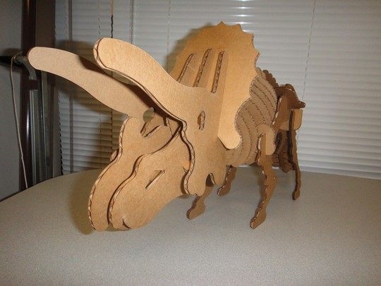
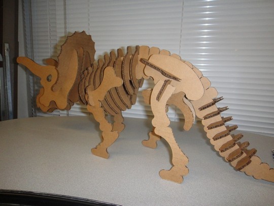
And voila! The completed Triceratops skeleton, in all of its glory! The press fits were nice and tight, so the structure held together quite nicely. This was a fabulous test, for now I have a huge cardboard dino in my office!
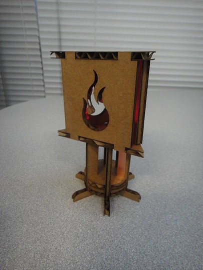
And now, for the real project, my Cardboard Lantern.
It arose from a simple idea, cardboard + LEDs = winning. I wanted to do some source of lighting involving a battery, copper tape, cardboard pieces, and one or more LEDs. What formed was a self-standing "lantern" of sorts with decorative "flame" panels.
I started with a coin battery, 3V, and designed a sandwiching mechanism that would allow me to adjust for error when clamping the battery to the copper tape pieces. This would ensure that there would be tight contact, allowing current to move through the pieces.
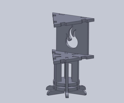
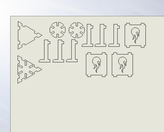
The slots were designed with the same tolerance, plus a little extra to account for the copper tape (so the width came out to be 0.149"). The walls were designed with a bit tighter of a tolerance (0.31" for the tab, 0.28" for the slot), with a 45 degree chamfer of 0.03". Each two pillars have opposite contacts to either side of the coin battery, so that a LED could plug into the top base and complete the circuit, as shown below to the right.
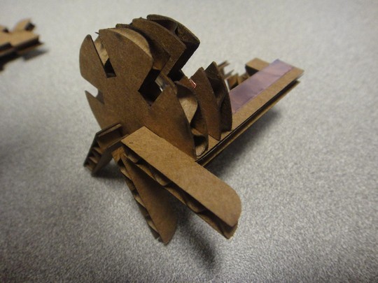
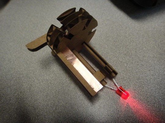
The copper tape adheres to the surfaces, then folds over the slots on the disk pieces and the triangle base, such that the pillars can make contact for the LEDs on top.
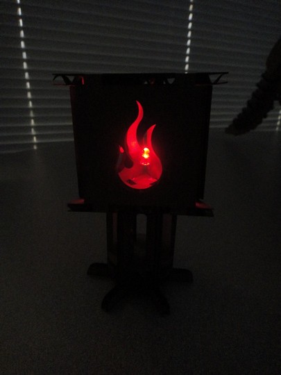
The press fits worked perfectly, and the contacts aligned very well. I am quite pleased at how this came out, and I hope you are too!