Making Almost Anything <-> MAS.863 <-> Fall 2011
Kristopher Dos Santos <-> Personal Robots Group
Week 3 <-> The FabISP

For this week's assignment, we were to cut, stuff, and program our very own programmer called the FabISP, designed to program AVR microcontrollers. We were given the .png file of the board to use on the Modela milling machine, and this little website right here showed me everything I needed to know about setting up the job:
http://fab.cba.mit.edu/content/processes/PCB/modela2.html
But just in case this is too long for you to sort it out, here are my procedures:
KDS's Guide to Not F*!@#ing Up Proceeding With Your Modela Job
- Prep the board by covering the back of it with double-sided tape. The tool forces will drag it around a lot so make sure it is covered.
- Align the board to the grid for simplicity in zeroing the tool, and MAKE SURE THERE IS A SACRIFICIAL PIECE UNDERNEATH IT.
- Make sure to turn off view mode for zeroing and tool change.
- Make a working directory on the comp attached to the modela, and drop the .png files for use in there (in this case, interior.png and traces.png). (You can do this from the command line using the command "mkdir".)
- Place your end mill in the tool holder by lightly tightening the set screw (height placement comes later).
- Set the origin by using the terminal command "rml_move <x> <y>". Note that coordinates are absolute.
- Set the Z by holding the Tool Down button, and leave about 3/4" between the stock and the chuck (part that holds the bit).
- Set the bit by dropping the bit onto the stock surface (BUT NOT LITERALLY DROPPING it), and tighten the bit with the set screws once the bit is in contact with the stock surface.
- Once the bit is set at the desired origin, use the following commands to send your first job (the one using a 1/64" end mill for the traces) to the modela
- png_path <filename>.png <filename>.path 1 0.4 4 # in out error diameter contours (png_path is the command, the other four are described by the comment line, indicated by the "#")
- path_rml <filename>.path <filename>.rml 4 ?? ?? -0.1 # in out speed x0 y0 z0 (the ?'s should be filled by you when you determine your origin. -0.1 is the suggested depth, but you may want to go a bit deeper, but no deeper than -0.145)
- rml_send_gui <filename> # for Bryan's super awesome Time Estimate GUI
- Do the same procedure to cut out the PCB with the 1/32" end mill, but this time, use the following commands:
- png_path <filename>.png <filename>.path 1 0.8 1 # in out error diameter contours
- path_rml <filename>.path <filename>.rml 0.5 ?? ?? -1.65 # in out speed x0 y0 z0 (again, use your specified origin for the ?'s, and the depth can vary between -1.65 and -1.75)
That's it! Watch your job very carefully, because it's very possible that things could happen. If they do, here's what to do:
- Hit the View button.
- Kill the command by entering Ctrl+C in the computer.
- Purge any other command by holding Tool Up and Down in View mode. It'll blink, then once the light is steady, commands have been purged.
And that's what I needed to do to save my board from being thrown around in the Modela. It seems that the sacrifical piece affected how my board would respond to the end mill. With that, I needed to use the notcher to cut out my board.
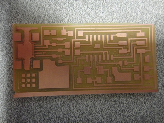
Also, due to the lack of leveling from the sacrificial board, I needed to do a couple of passes for the trace to be fully cut.
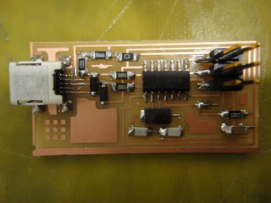
Moving on, it was time to stuff the board.
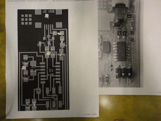
Since there was no component list, I used the two board pictures provided to pick out all of the board components, and place them on the picture. This way, I knew where each one belonged when I began to stuff the board. Now, my soldering technique has been refined from many months of mistakes experience, and here's what I got.
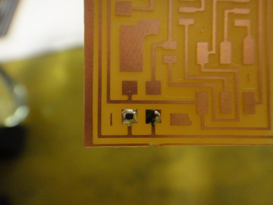
- First, prep one pad with a nice puddle of solder.
- Then, grab your component with a pair of tweezers, and heat up the puddle with the soldering iron.
- Place one end of the component into the puddle, holding it firmly, and remove the soldering iron. MAKE SURE THE COMPONENT IS FLAT ON THE PAD, AND NOT RESTING ON THE TOP OF THE SOLDER.
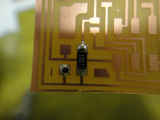
- Finally, heat up the other end and hit it with a good bit of solder, shown above.
Voila! A component is now successfully placed onto the board!
Now, to program this little guy...
As hinted from Mr. X-to-the-Z Xzibit above, I used a FabISP from last year to program my programmer. Since I was using Windows, I tried to use WinAVR, but no luck. I instead turned to Cygwin and did everything from the command line. Here's what I did:
- Make sure that when using another FabISP to program your FabISP, the SJ2 jumper needs to be closed on both programmers to provide power to the target board.
- Download "firmware.zip", the WinAVR package, and the Windows TinyUSB driver (just unzip to the Desktop).
- Connect the 6-pin connector from the programmer to the target board, matching pin 1 to pin 1, etc. Then, plug in the programmer into the computer via USB. When it searches for software, direct the wizard to the TinyUSB driver folder.
- From Cygwin, use the command cd to get to the firmware folder, and have that set up for now.
- Open up the Makefile in WORDPAD, NOT NOTEPAD (WordPad will have everything organized nicely). You'll see these lines:
- #AVRDUDE = avrdude -c usbtiny -p $(DEVICE) # edit this line for your programmer
- AVRDUDE = avrdude -c avrisp2 -P usb -p $(DEVICE) # edit this line for your programmer
- You'll want to uncomment (remove the #) from the line that has usbtiny, and comment (place #) on the line that has avrisp2
- Save the Makefile. Now, run the following commands in Cygwin:
- make clean
- make hex
- make fuse
- make program
And there you have it! The programmer should be all set! Just remember to remove SJ1 once you are done. Hope this helps everyone else!
Back to home