I had big dreams for the Make Something Big assignment, and it involved moving parts. I wanted to make a mode of transportation, such as a bicycle, or a diwheel, or... a monowheel!
I remembered seeing one of these in an anime flick called Steamboy. The protagonist had a steam-powered motorcycle in which a big outer wheel was spinnning along an inner frame, and he sat inside of it, turning by shifting his body weight back and forth. And by doing a bit of research, I was surprised to find that this wasn't science fiction; there are actually a couple of companies that make these motor-powered "monocycles", as well as DIYers who have made their own. But I wanted to make a human-powered one, a "monowheel".
I did what any smart engineer would do when creating something new - find out what exists. As it turns out, there have been hundreds of patents that have been made for the monowheel, as well as working designs all around the world. One such monowheel interested me: Ben Wilson (at right, website is here) and his monowheel. He designed this as part of an expo in Tokyo, and it was just the inspiration I needed to design my own. Since most of the designs used standard bike parts (crank, sprocket, chain), I figured I would design the rest of it, and somehow obtain those necessary parts. I divided the bike into 4 sections:
And so, with two weeks, my good friend SolidWorks, my old buddy the waterjet, and my new acquaintance the ShopBot at my disposal, I set out to work on my very own Monowheel.
The given piece of OSB was too thin to make a sturdy frame, even with it doubled up. I was going to need something more solid in combination. I decided to purchase a piece of 23/32" RTD sheathing plywood from Home Depot (among other things), and use it (doubled) as the core. Then, I planned to sandwich it with the OSB, giving me a stable, 2.3125" thick frame.
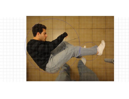
To design the frame, I had two pictures taken: one of me on the floor of my kitchen, and one of just the tile floor, with as little misalignment as possible. I needed the picture to appear as a grid so that I could utilize it for measuring. Once I merged the two photos using the magic of Photoshop, I imported the picture into a SolidWorks drawing, then turned on the grid and set it to the size of the tiles. Once I did that, I scaled the imported picture to be exactly the correct size as in the real world, so that I could use my body image as a measuring object. As shown, I began by drawing a circle around my body to see what the inner frame would be, and another to show the path of my feet so as to place the crank. Once I had this measurement, I moved to SolidWorks to design the frames.
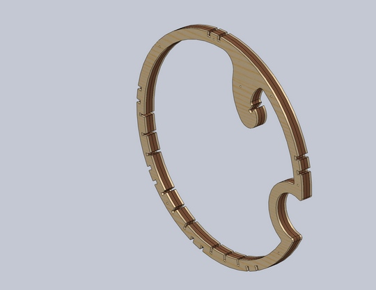
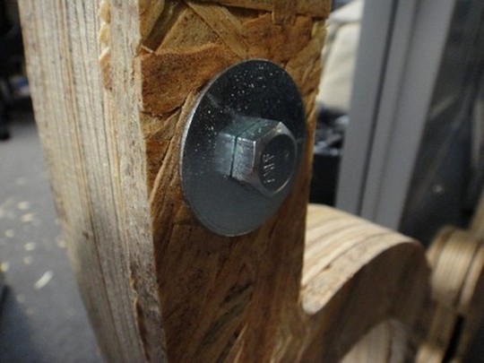
I made the frames by drawing one part file with the design, and copying it onto a similar part with a different thickness. Then, in the assembly, I sandwiched them all together and planned to use bolts for fastening. I didn't trust press fit locks to hold together the frame, so I went with something more traditional. I chose to use 3/8" hex bolts with 1-1/2" washers on either side to distribute the pressure evenly on the wood. For the rest of the frame, I designed notches for the bearing blocks, the chair, and the handlebars, as well as a space for the drive wheel. I only knew that I was using a 7" mower wheel, so I made sure to leave enough of a gap to house it, and then edit it later once I had modeled a tire and drive train.
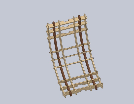
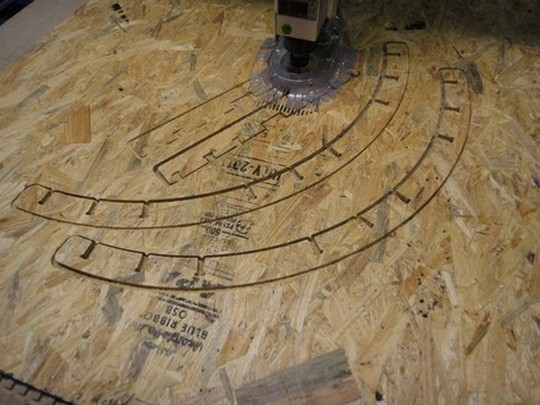
The chair was a thatched design of many pieces of OSB and plywood. To make it, I first estimated a width that would be comfortable for sitting, and made a slat with notches for the inner frame and other pieces. Given the amount of material I had and the space I needed to cover, I went with using nine slats spaced along the inner frame, carefully avoiding the bearing block locations. Then, I took the inner frame parts, copied them, and cut them into "ribs", four OSB and two plywood ribs. Put all together along the frame, this provided a sturdy seat for me to ride in the monowheel. As shown on the right, the handlebars I designed were nothing special; I made a curved piece with finger grooves out of the plywood, and hooked it into the inner frame. This way, I would be pulling it into the press fit, instead of pulling it out of one.
I needed some sort of caster system to allow a tire to ride smoothly along this frame. Looking back at Ben's design, I noticed that he used a system of hourglass rollers. This allowed the tire to roll along the frame without rolling out of it. However, finding small hourglass rollers was an impossible task, and was not cost effective at all. Instead, I decided to do something similar, but utilized stock parts to do so.
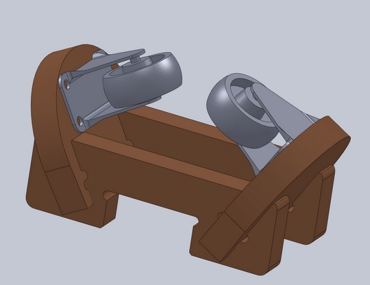
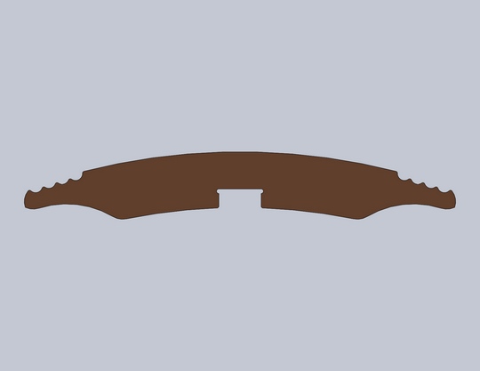
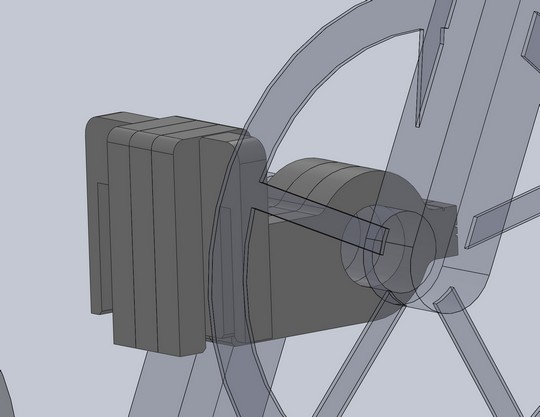
I used 2" rigid casters from Home Depot and made a "block" to position them at angles. I oriented them at 30 degrees from horizontal so that the holding pieces would have enough wood in the press fit to hold them steady at 60 degrees. For alignment, I made the edges flush with the top surface of the bottom brackets so I could easily align them. And yes, I did model the casters from scratch... with a pair of calipers and a steady hand. Originally, I was going to try to press fit the block along a curve, but realized that it doesn't exactly work that way. The bearing black fits into the frame straight, sliding in radially and flush with the edge of the frame. Also, the holding pieces are at an advantage of being at an outward angle, since it is easier to press fit into the block.
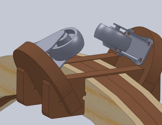
I knew I'd have to secure some bike parts from somewhere; luckily, Adam Setapen had a leftover crank. However, I needed some other parts, so I popped over to Cambridge Bicycle to obtain pedals, a freewheel back sprocket, and a chain. Once I had these modeled up (approximately), I placed them in my model and began designing around them. The outer frame for the drive train was not going to be wood (I needed something more durable) and went with Delrin plates, one of 1/2" thickness, and one of 1/4" thickness. These were going to be cut on the waterjet, along with the other pieces that I used to secure the other parts. To place the crank, I once again used my position drawing to see where I'd be pedaling, and designed the outer frame accordingly.
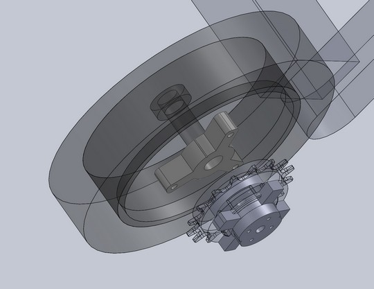
The other pieces I designed out of Delrin were for three things. First, I used the 1/2" Delrin to design a locking hub for the drive wheel. The rod stock I was going to use would not press fit into the wheel, and so I needed to make a hub for it (shown on the left). I cut this on the waterjet, and then using a little trick I learned, I designed a notch that would give me a center for drilling and tapping a threaded path for a set screw. It's a simple trick: wherever one needs to put a set screw, design a notch 0.03" wide by 0.04" deep into the edge where the hole needs to be. The water jet will cut out this notch in your part, and voila! Just secure it with a vice, take it under a drill press, and make the hole! The same rule went for designing a hub for the sprocket. I designed this in three parts. One piece would be the lock hub, having two set screws for securing. The next piece would press fit into the cross-like pattern on the face of the sprocket. The last piece, which had the threads for the bolt circle, would fit inside the sprocket. The whole thing would be screwed together to clamp on the freewheel part of the sprocket, and be able to lock onto the shaft. I used the 1/4" Delrin to do this. The last thing I designed was for the crank bearing. I used the 1/2" Delrin to design a lock piece for the frame, then cut a notch for three pieces of the 1/2" Delrin. Then, I designed a piece that would press fit on one end, and act as a shaft collar on the other. The shaft collar end uses the notching trick for set screws, plus two other notches for post-water-jet cutting. (The whole piece needs to be solid to ensure an aligned hole for the locking screw). Tap one end, drill out a clearance hole on the other, and presto! A custom shaft collar, or in this case, a crank bearing collar.
This was a difficult decision to make. Since no one made a tire big enough for what I needed, I was going to have to make a tire myself. I wanted a light material that could easily bend and take shape to a perfect circle. I thought, and I decided to go with PVC. The design was (seemingly) simple: bend two sections of PVC around a curving block with the correct curvature, and adhere them together using PVC cement. I read a tutorial online on how to bend PVC; it seemed simple enough. Fill the pipe with sand, use a heat gun, and bend it to your will.
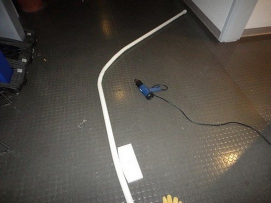
However, it was not that easy. The PVC was not bending the way I wanted it to, and I quickly determined that this was not the best way. With some consultation, I decided to try to cast a hard rubber wheel for next week's molding and casting assignment. Hopefully this would prove to be a better method of making my own tire. Thankfully, I can still use the model of the tire I made in SolidWorks to make the mold for the tire.
Here are the press fit settings I used for each material:
Oddly enough, the whole frame notch fit together snugly, which was surprising based on the settings I used.
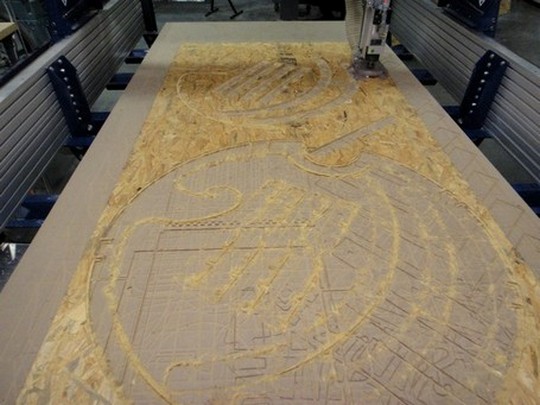
The ShopBot settings I used were the same for both pieces of wood (10,000RPM, 160 in/min feed), and I used a thickness of 0.76" for the plywood and 0.47" for the OSB. As seen above, some of it didn't cut all the way through, which was odd, since one side cut out smoothly, while the other did not. This was probably due to an unlevel placement of the wood.
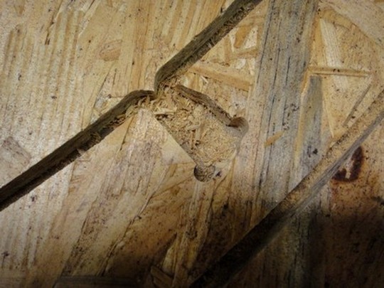
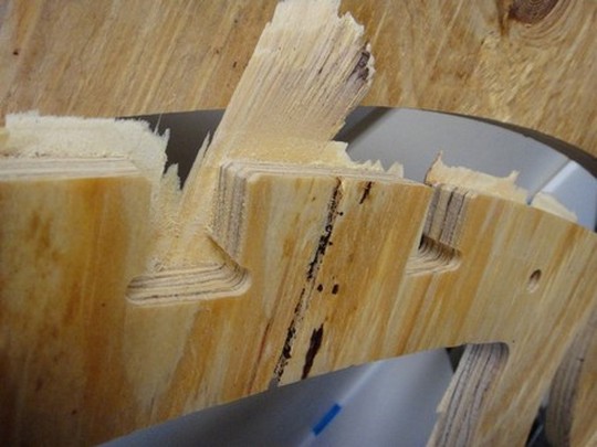
Also, I noticed how setting the toolpath can affect how pieces are cut. My rib piece was badly wounded after it cut all the way through and got shifted into the end mill. Setting the start of the cut to the outer edge of the rib would have been wiser.
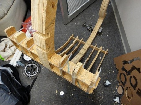

Since the chair's slats and ribs were loose (especially with that ugly notch on one of them), I used some good old wood glue and zip ties to set them in place. The end result made it much stronger and more stable. No more wobbly slats!
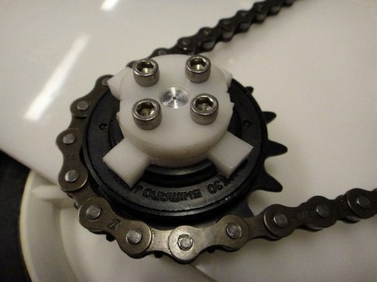
The water jet pieces all turned out fantastically, save for the cross clamp. I needed to thin up the press fit pieces since they were locking up the sprocket and wouldn't allow it to turn freely. Other than that, it came together very nicely. I had to widen the hole for one of the crank bearing collars to fit over the threaded part, but everything press fit and clamped down perfectly. I needed a mallet to completely press fit it together, but it was to be expected. The settings I used to cut the pieces were General Plastics, Quality 4, and 0.53" (0.27" for the 1/4" piece).
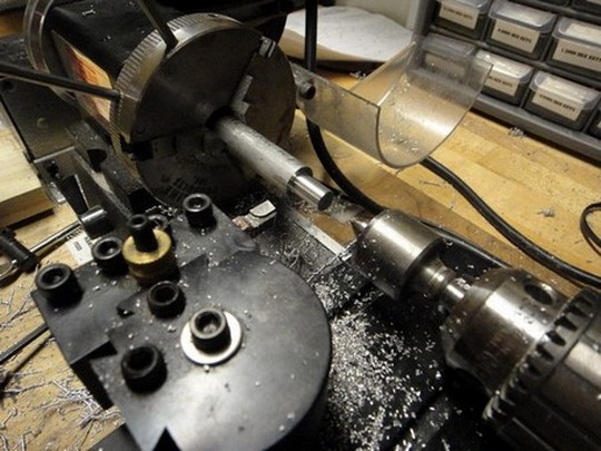
The custom shaft for the drive wheel took a little bit of my previous skills to fabricate. I used some 1/2" aluminum rod stock and cut it down to size to fit inside the Delrin frame. Then, I turned down the two ends to fit into 5/16" ID bearings, which were press fit into the Delrin frames. It turned out perfectly! The shaft fits beautifully in the bearings, and the drive wheel rotates without any problems!

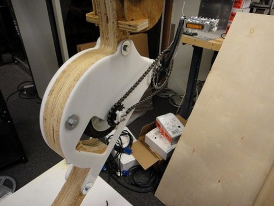
Fitting the chain to the gears was a bit trickier than expected. The big chainring was a little bent, which made chain alignment difficult, and the chain length was too loose. I switched to the smaller chainring to get a tighter fit, but the chain was still not tight enough. I wound up pressing a polished shaft on the bottom to act as a tensioner, and that worked pretty well. A little noisy, but it rotates really well.
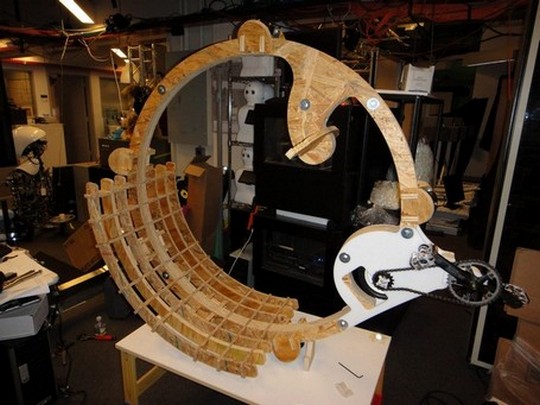
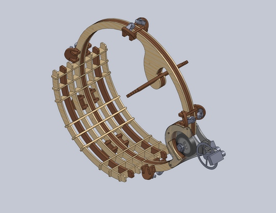
And here it is, built in all of its glory! Next week, I'll hopefully cast a tire for this thing, and with my luck, it will be a functioning monowheel! No casting, just gonna be a new source of pipes. Will update when new tire is created!