This week, I got to tackle what I was looking forward to learning: embedded programming. Once again, I had plans... I had a super plan to execute once I got past this simple LED blink board. But I had to get past the LED board first, which proved more difficult than expected.
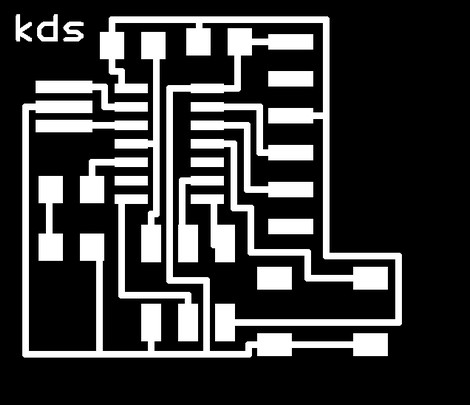
I had previous experience using Eagle, and creating my modified "hello.ftdi.44" board. I noticed that our designated switch was a SPST (single-pole-single_throw) switch, and quickly realized (with the help of an EE buddy) that if I connected the relay between my desired pin and ground, then every time I pushed the button, I would be pulling the pin "low", which provided me with some insight on how I would go about programming my blinker code. No connection to VCC necessary; as long as I had either one of the ends connected to my input pin, the other two sides (or one, since two pins on the button could just solder down for support, and not be connected to anything, as long as those pads are on opposite sides of the switch) could be grounded, and I'd get the same effect. Cool. I put my insignia on the board and did the usual prep steps for the modela: turned off all but the top layer, exported it as a 500 dpi image in monochrome, and ported it to the modela comp.
This is where things got interesting. And by interesting, I mean horribly wrong. Apparrently, the .path flipped my image such that it was milling inside the traces. That's not good. I ported the image through the fab modules, and sure enough, the path.png showed that the traces were being milled. Thinking that low resolution was the culprit, I exported the image again, this time at 1000 dpi. No dice. I couldn't figure it out for the life of me. Then, on a whim, I ported the image into GIMP, copied it, and pasted it into a new .png, and then sent it through the fab modules. Sure enough it worked (don't ask me how).
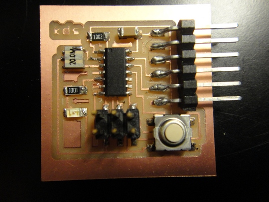
So, after milling a board, stuffing it, breaking it, and then milling another board using multiple z passes, I got this little beauty above. Important things to note about testing Neil's "hello.echo" code for you Windows users out there using Cygwin:
Once you've done that, you can run the "hello.echo" file (assuming you bootloaded the code).
Now, to get the code for blinking the LED. Here's my C code for doing this:
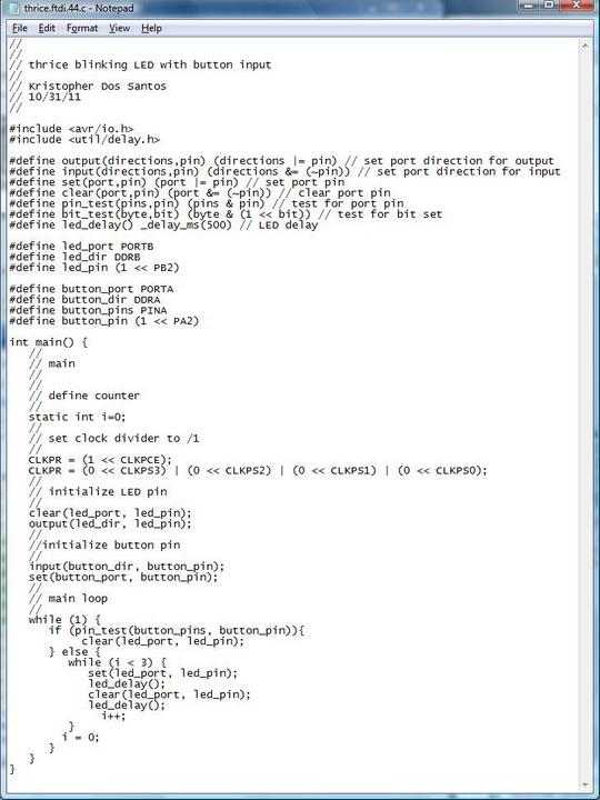
I had to do a bit of reverse-engineering and research to get this done. I noticed that Neil used definitions to set the pins, so I kept that in my code. The LED and button definitions were based on where they were located on the specific side of the ATTiny44 (A side or B side). Then, I set the LED pin "high" and the button pin "low", and in my main loop, tested to see if the button pin was high or low. The button being pressed would drive it "low", and that activated my loop to blink the LED as many times as I saw fit. The above code blinks it three times with the use of a counter. I also put delays to hold the LED on or off for a good length of time (to make sure it was working properly).
Below is a .gif of it blinking. Enjoy!