Fabrication, much like war, is the realm of uncertainty.
For my first assignment, I decided to show some school pride and create a model of the MIT Dome. Not only it would be a nice addition to the bare shelves in my office, it could help in the planning of the next police-car-on-top-of-the-dome hack. The MIT Sloan logo was my reference. After drawing a sketch on a piece of paper, I used GIMP and Inkscape to convert a JPG I found over the web to an SVG file and then to DXF for AutoCAD. It’s kinda funny how each software package supports about 30 different file formats, and yet there’s so little overlap.
The next day I spent almost two hours at RPL getting the lasercutter to print. Eventually I managed, with some help from Skylar and Justin, to find the proper settings and print a simple rectangle (check out my settings below). By then it was already time to hand over the cutter to the next student. Such a bad luck.
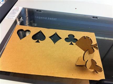
I decided to go with a simpler design in order to meet the deadline. The bad luck I had with the cutter made me think of making playing cards. I grabbed some SVGs from Nokia developer’s web site and edited them using Inkscape. Back at the shop, I opened the DXF drawing in AutoCAD and made some last minutes adjustments. I already knew the printer driver settings by heart, so printing was a breeze and I even had some time to experiment with other shapes and power levels.
")


Overall I was happy with the outcome; so was my neighbor, who’s about to give birth and asked me to make a child-friendly version made of wood. This would also require deeper notches and chamfers, which I plan to add as soon as I get better in using parameters.
Reading posts by students from previous years, one gets the impression that fabrication is fun and easy. However, as I tried to demonstrate in my post, this is not quite true, as the learning curve is brutal and there’s a lot of trial and error involved. The outcome is worth it, though. So keep the faith and remember the first cut is the deepest -- unless you use the proper settings of course.