This week was all about sensors, and I decided to make as device to measure the level of liquid in a glass or bottle. Neil advised me liquid level could be measured via capacitance, so I set forth to make the step responses sensor. Also on the agenda for this week were experimenting with the vinylcutter and set up my new computer (a Mac) with the programs and drivers required to design, program, and test boards.
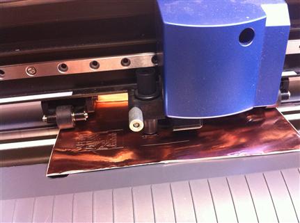
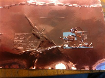
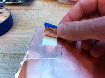
My first stop was the vinylcutter. I loaded the default settings for copper and kept changing them, but was unsuccessful until Toni suggested that I change the bit. That was a good call, and I finally struck gold (or rather copper) with force 50/velocity 1.5 in the fab modules and -0.25 pen force on the cutter. The board peeled very well but the rest of the weeding didn't go as nice. I promised myself to practice weeding sometime else and moved on to mill.
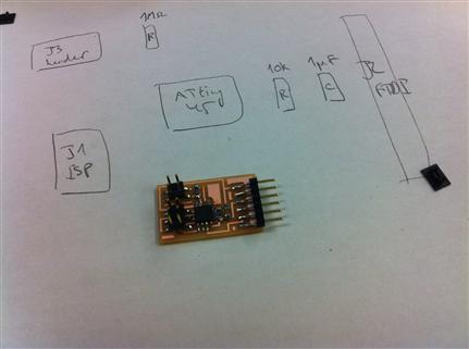
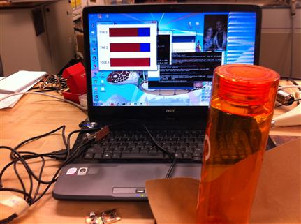
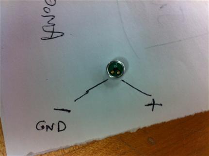
I milled the load board on the Modela, stuffed it, and connected the 2x2 header four plates, as shown on Matt Blackshaw's site from last year. Once programmed, the board measured pressure (i.e., resistance) quite well, but wasn't very useful for measuring liquid level (i.e., capacitance) between two copper pads taped to a bottle. While trying to figure this out, I made the light sensor board. And the step response TX/RX board too. And the microphone, which unfortunately I didn't complete because we ran out of 0.1uF capacitors at the Arch shop.
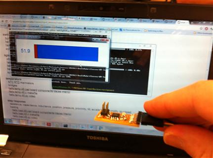
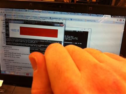
The light sensor worked very well, but the real surprise was the TX/RX board, with which I could finally measure the water level in the bottle. As it turns out, the load board and the TX/RX board measure in different ways. The load board supposed to be connected to a single pad only, whereas the TX/RX should be connected to two. This is why the latter succeeded where the former failed. This worked very well at the shop, the value on the screen decreasing as water was added. I also learned that very small changes to the bit_delay_time (even 1 ms) can compensate for irregularities in microcontroller clock speed, and significantly change the values received by the terminal program.
I repeated the experiment at home with a measuring cup, looking to calibrate the terminal values against a pint glass. The results were quite peculiar this time, when the cup went from 3600-4000 when empty, to 22700-22900 at 200ml, -34500 to -34900 at 300ml, and then up again to -22400 to -22600 at a pint!
As for configuring the new Mac, that went pretty smoothly thanks to the UNIX shell and the pre-installed Python (see instructions below). Ironically, the only task I needed my PC for was to retrieve the photos from my iPhone: for some reason, the photo software wasn't installed.
