FabECG: a simple electrocardiogram board
Marblestone / Fracchia
Technologies for rudimentary physiological sensing are getting cheaper and easier to implement. Consider, for instance, these non-contact sensors from UCSD which can be used to take an EEG through hair or an ECG through a T-shirt! One can even make a simple oscilloscope to digitize, store and view the signal using only a Tiny45 micro-controller and a laptop: tiny45 oscilloscope
Cool general-purpose commercial hardware in this category (from IMEC). And a nice book on ECG.
This week Charles Fracchia and I made a simple electro-cardiogram board (see also Charles's documentation here) which should also be in principle capable of EEG and many other such differential voltage measurements on the skin, especially once digital post-processing of the signal is implemented. The system uses the soft fabric electrodes from the headband of the Zeo Mobile EEG headset. This required the sacrifice of one Zeo but in the future this should be easy to mimic using home-made fabric electrodes or other non-contact sensors.
DISCLAIMER: We make no claims about the safety of the below techniques or about their appropriateness for any purpose. Use at your own risk and consult experts on electronics safety.
We based the system on two references: Chipstein's EEG circuit and this EEG circuit from Charles Moyes and Mengxiang Jiang at Cornell.
For digitizing the amplified ECG signal, we also borrowed this Arduino and Processing code from Chipstein and used this Matlab code modified from the Cornell team, in conjunction with this Arduino code for grabbing the samples.
Circuit design
Schematic: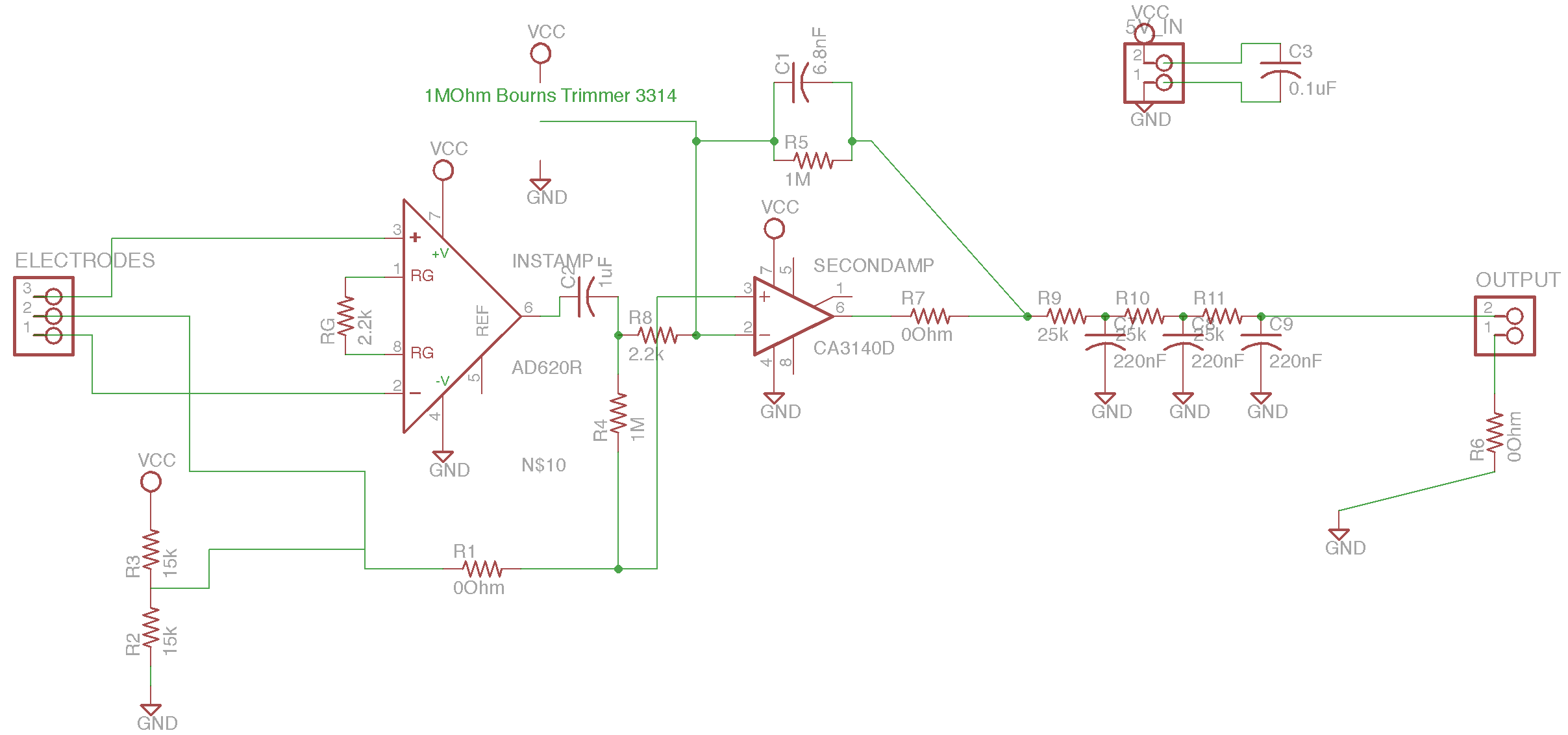
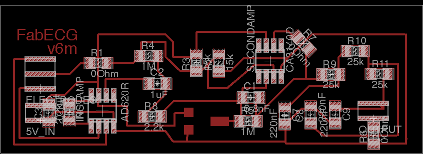
Single-sided PCB:
Eagle Files: .zip
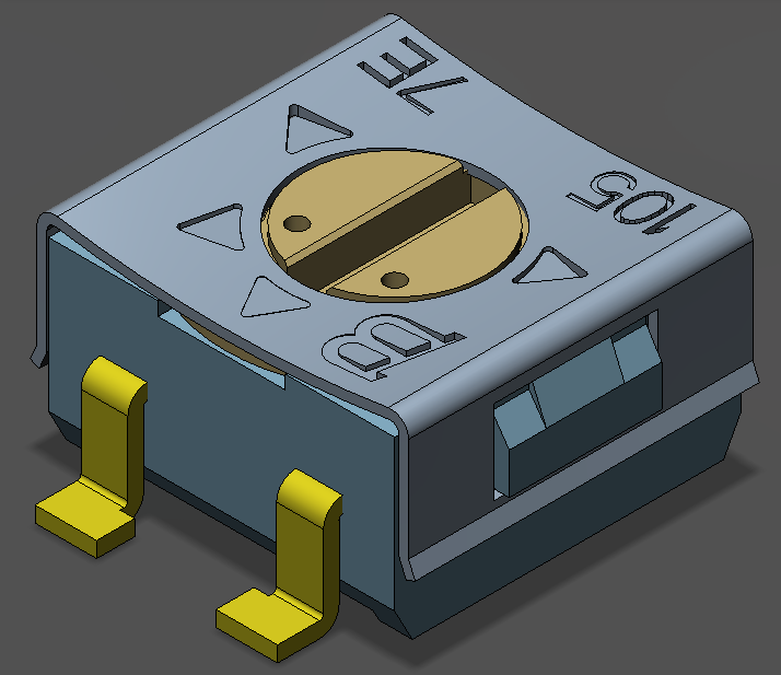
Part list: .txt and don't forget the 3314 1M surface mount trimmer from Bourns for the PCB version.
Following the same idea as the Chipstein and Cornell designs, the circuit uses an instrumentation amplifier (the AD620) to take the voltage difference between two spots on the body. A second amplifier (the CA3140) amplifies this differential signal. A potentiometer is used to siphon off current from the negative input of the second amplifier, and tuned to remove the DC offset resulting from the inevitable and unpredictable static voltage differences between any two spots on the body: unless removed, the DC offset causes the second amplifier to saturate its output at power or ground. Because we power the amplifiers using only the +5V and ground levels from an Arduino (or other micro-controller board), we need to split the supplies for the amplifiers, which require both a positive and a negative supply line. To do so, we use a voltage divider circuit to define a virtual ground at 5V/2 = 2.5V, and then use +5V and Arduino ground as the positive and negative supply lines, respectively. An electrode held at ground electrode is also placed on the body at a third location. Low and high pass filtering are performed in-between amplification steps and during the second amplification step, and then a bank of three low-pass filters follows after amplification to remove additional 60 Hz noise. Those interested in understanding the exact frequency response of the system should do a full calculation (e.g., using the Op Amp golden rules and the rules for frequency-dependent impedance of resistors and capacitors) or a Spice simulation, because the filters going into and through the second amplification stage cannot be treated simply as individual high and low pass filters in series. In addition to serving as the power source, the Arduino is also used to sample the amplified signal through one of its analog input ports and to shuttle the signal to a computer over serial.
According to the data sheet: Gain = (49.9 kOhm / R_G) + 1 where R_G is the gain resistor. Therefore a 49.4 * (10^3)/22 = 2.2 kOhm R_G resistor leads to a gain in the first stage of amplification of around 23. The second amplifier should give an additional factor of around 1 megaOhm/(2.2 kOhm) = 455. The filtering may remove some frequency components. So the total gain is over 1e4, theoretically. In the below, we're usually measuring signals of around 1V, which is about 1000x higher than the millivolt-range signals characteristic of ECG, even after filtering, and even using the fabric electrodes.
Breadboard version
Breadboard prototype: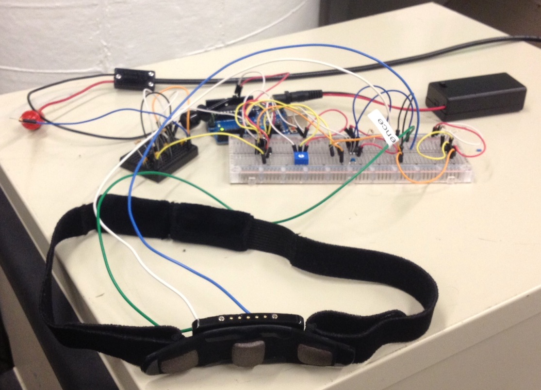
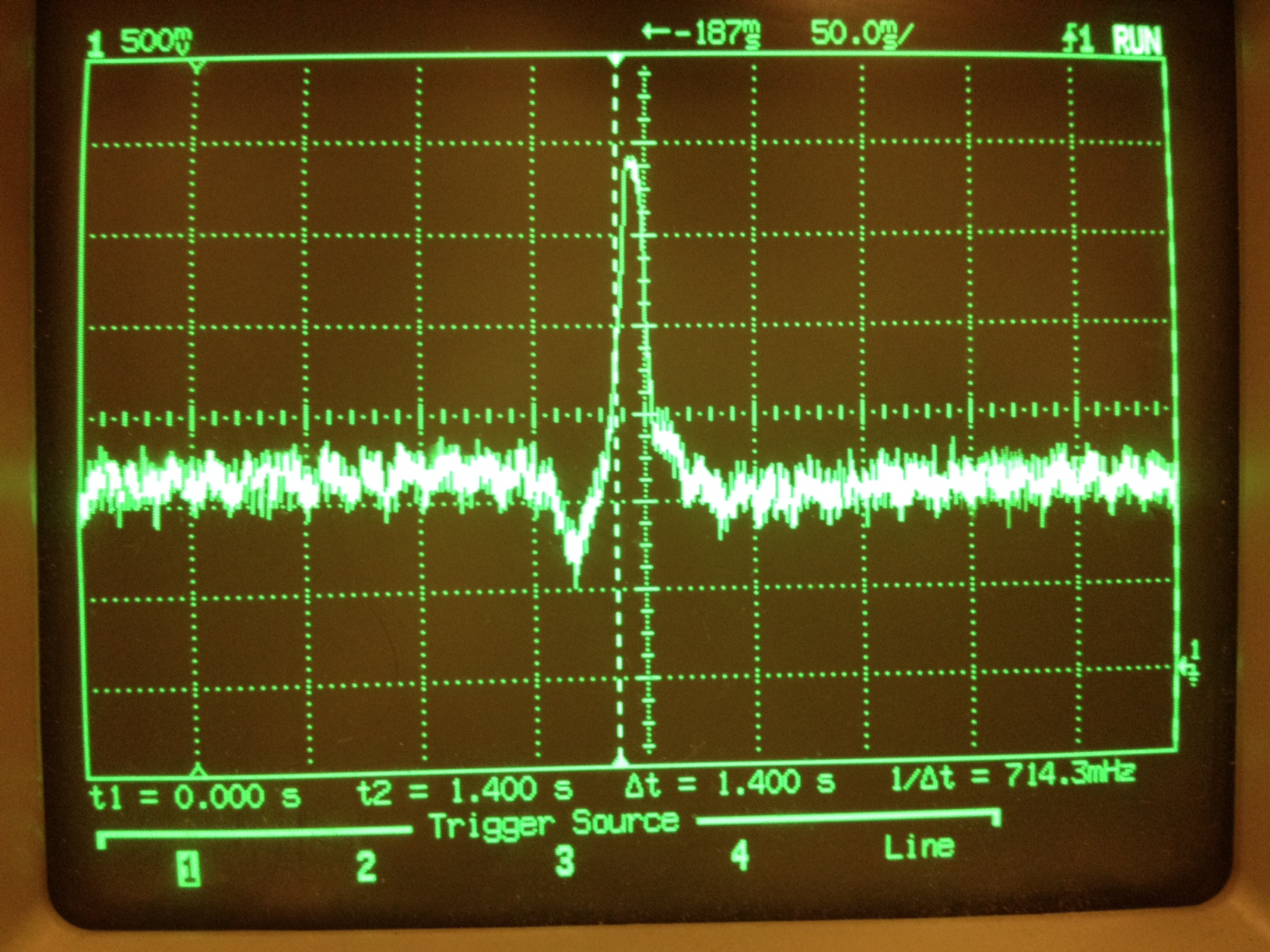
First electrocardiogram result (via an oscilloscope):
obtained by holding the Zeo headband inputs (see below) firmly against the skin of the left chest
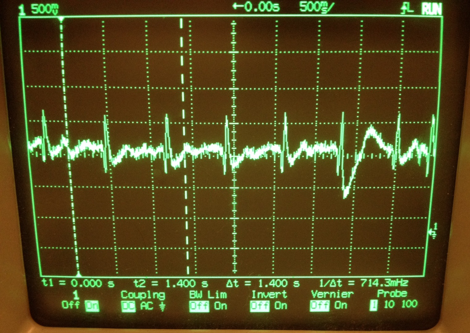
You can see the effect of moving around and disrupting the electrode contact momentarily.
Triggering on the signal:
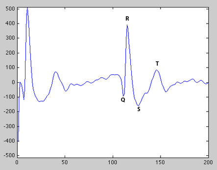
Arduino/Matlab acquisition (see below): annotated with labels for characteristic ECG signal features
Arduino/Processing acquisition (see below):
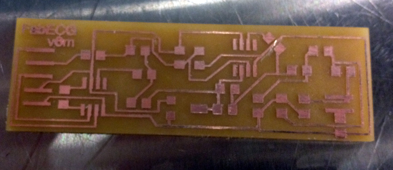
Single-sided PCB
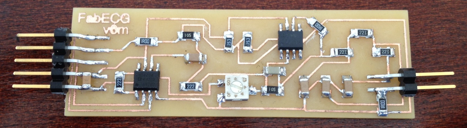
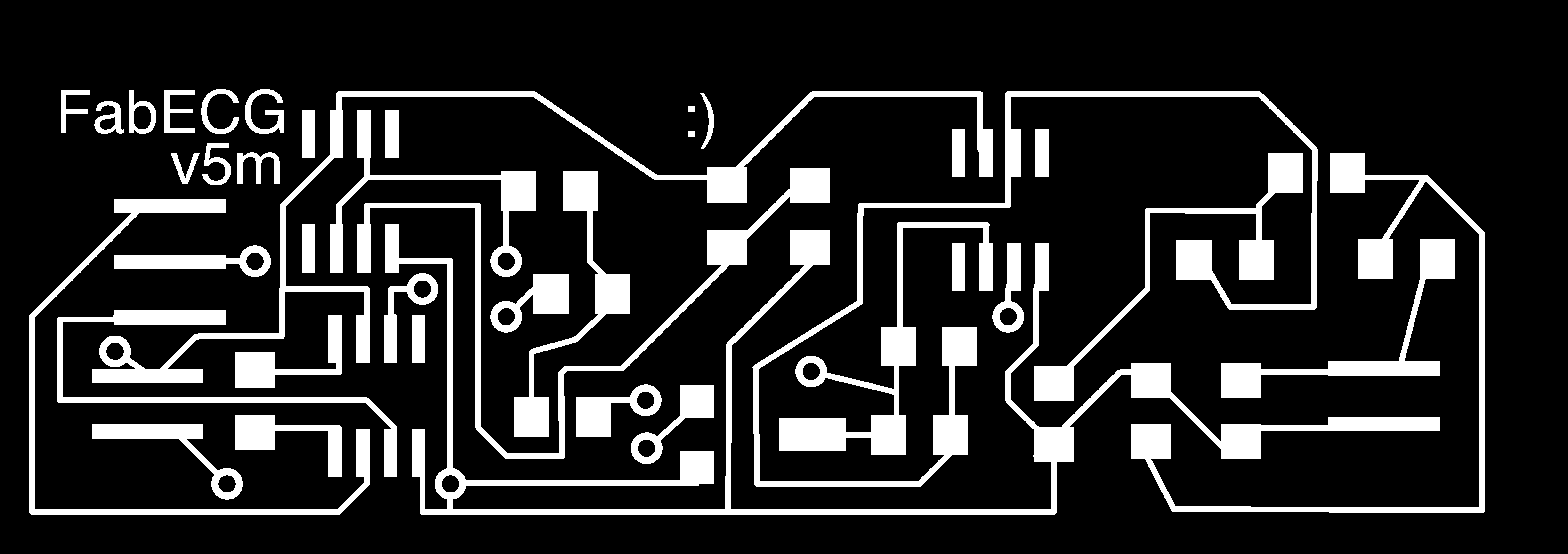
We added zero ohm resistors to allow one trace to hop over another and routed the circuit using Eagle software. We then milled the traces on a Roland MODELA mini mill using a 1/64 inch end-mill and a 1/32 inch end-mill to cut out the border of the board. To do so, we exported PNG files from Eagle at 2300 dpi resolution and the processed them and sent them to the MODELA using the Fab Modules software. The top layer was used for the traces and the dimension layer for the board boundary. For the board version we replaced the 6.8 pF feedback capacitor C1 with a 10 nF capacitor and the 25 kOhm resistors in the filter bank with 22 kOhm resistors, with no negative effect.
Traces (click for full-sized):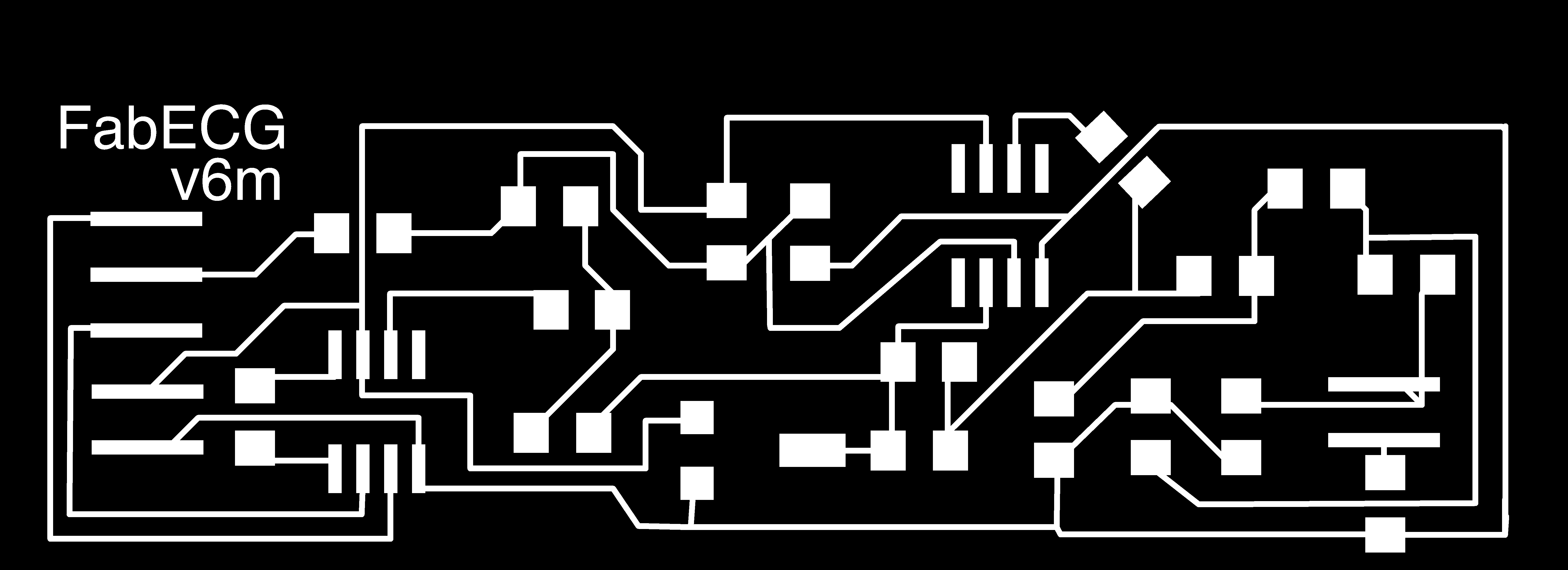

Here is a picture of the 1M trimmer geometry:
Milled traces:
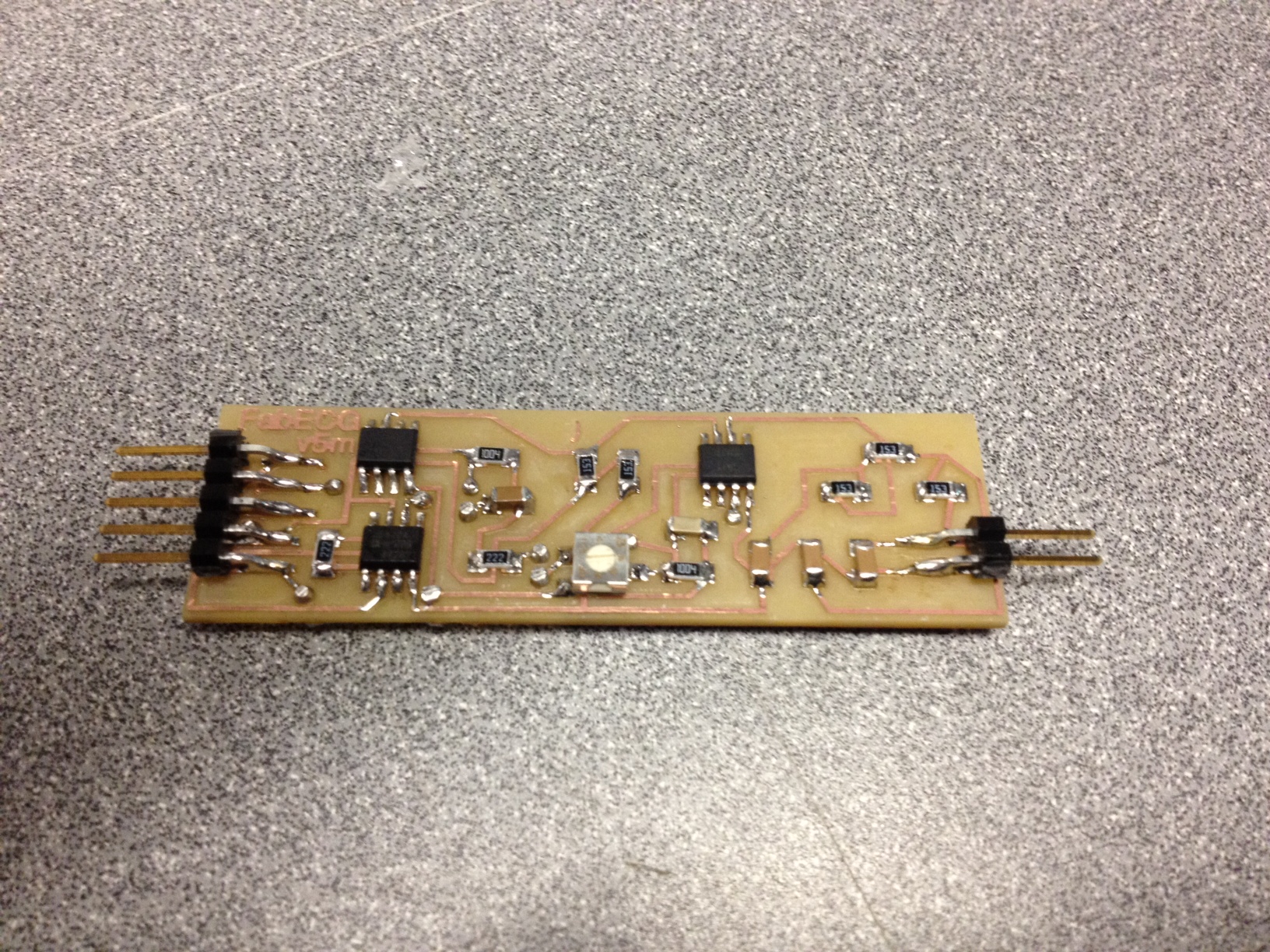
Stuffed board:
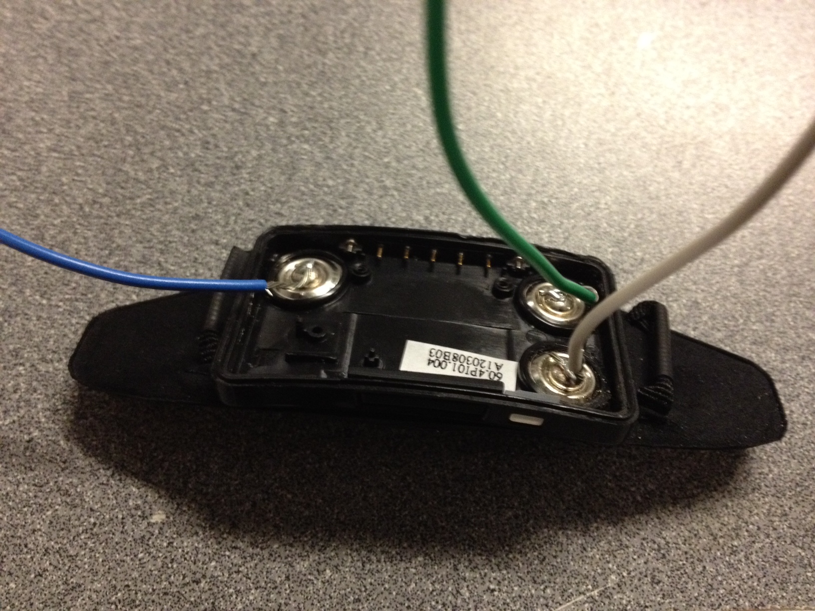
Electrode hookup
We removed the electrode assembly from the Zeo and directly soldered wires to the electrodes to serve as inputs to the AD620 instrumentation amplifier. The green wire here goes to the virtual ground.
Data acquisition
A full setup with the Arduino for power and acquisition is shown here: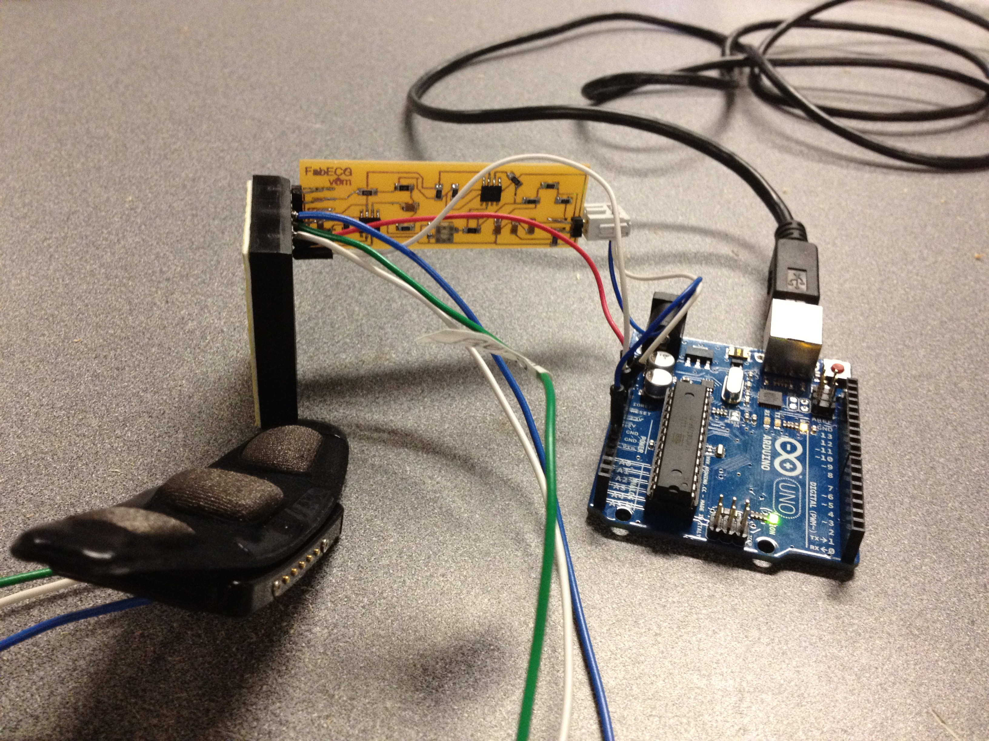
On the left side of the FabECG, the board receives power and ground from the Arduino through a 5-pin header (connected to Arduino via a small breadboard, here) as well as the three electrode inputs, the middle being the reference electrode held at the 2.5V virtual ground. The Arduino is connected to my MacBook Pro via a USB cable which provides both power and serial communication. Disconnect your computer from the wall power and run it off its battery here: do not connect a computer hooked up to the power line to your body, even through intermediates such as the Arduino and FabECG board.
On the right side of the FabECG, it outputs an instance of the Arduino ground as well as the amplified ECG signal output, which is fed into the Arduino's analog input A0 through a home-made cable. We wrote several scripts for the Arduino too see how fast we could get it to sample and send data over serial. There is a nice article about Arduino data acquisition here. At 9600-baud serial you're forced into the 10 ms range for inter-sample interval (unless you want to use additional memory to form large buffers that store many samples taken faster than the speed of serial), so typically these use higher baud rates. These allow you to debug the sampling just by viewing the serial monitor.
A version based on interrupts which gives 4 ms sampling interval at 57600 baud serial (based on this code): .ino
We also borrowed this Arduino and Processing code from Chipstein and used this Matlab code modified from the Cornell team, in conjunction with this Arduino code for grabbing the samples.
Removing DC offset
To remove the DC offset, hold the electrode assembly against your body at the measurement site. Then adjust the potentiometer until you see fluctuations in the output. If the output (referenced to arduino ground) is saturated at 0V or 5V, then you need to adjust the potentiometer. You should see a relatively sharp window where the output goes from high to low. The system needs to be biased in that sloped region to perform any measurement. Luckily we were able to find a nice 1 Mega-Ohm surface mount trimmer potentiometer from Bourns for this purpose. To quickly find the approximate spot, you can short together all of the input pins and adjust the output to around 2.5V which is half way between power and ground, as the out output should be near the virtual ground for a null signal.
Results for different signals
Adam's hands (with reference and one electrode on right thumb and the 3rd electrode on left thumb ):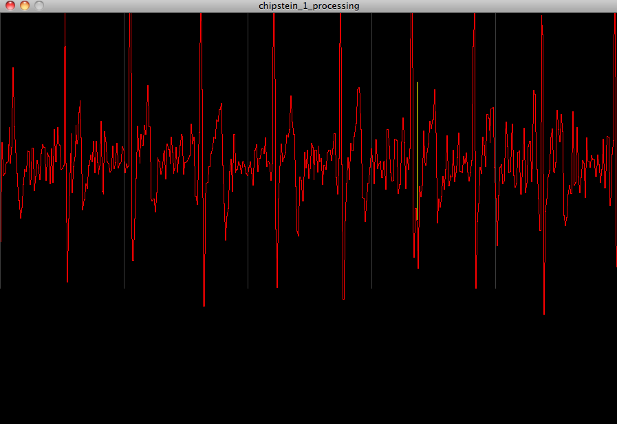
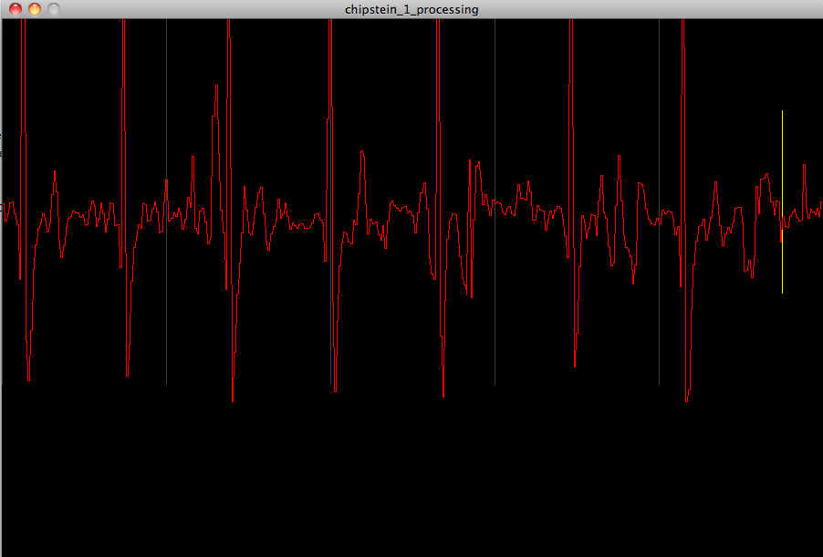
Charles's heart via chest:
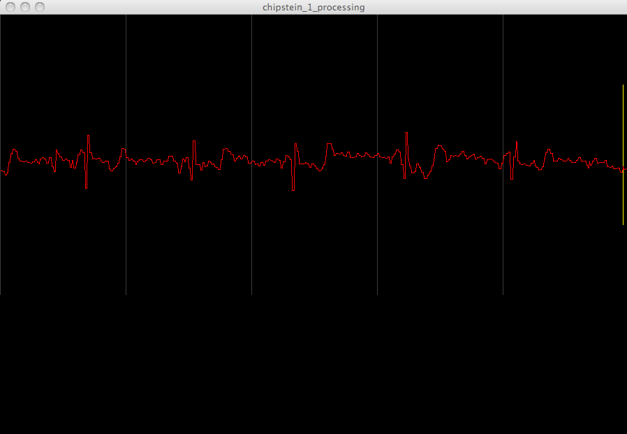
Charles's pulse via throat:
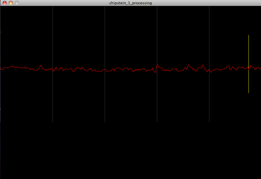
Charles's forehead (probably too noisy for EEG):
Making more complex 2-sided boards on the Modela
We also experimented with making more complex board designs on the Modela including two-sided boards with vias, although we haven't yet made one of these fully functional. The via size needed to be set sufficiently high in order for Fab Modules to recognize that we wanted a hole there. After cutting out the top traces we cut the vias and the board outline, then flipped the board vertically and stuck it firmly in the upper left hand corner of the region which had been removed from the board stock. We also flipped the bottom-side traces PNG file vertically and then milled the bottom traces with a starting-position offset of -1/32 inch ~ 0.8 mm in the x and y directions.
The cutoff size for hole diameter to mill vias was slightly less than that of the 1/32 inch = 31.25 mils = 0.8 mm end mill itself, namely, > 30 mils. Otherwise the Fab Modules software did not identify the hole in making the tool path. We could also adjust the tool diameter in the fab modules to force it to find holes of different sizes. Thus, sufficiently-large via pads were necessary. The larger the better since the procedure used here to align the top and bottom layers is not very precise, meaning that some wiggle-room is needed so that the bottom traces contact the via pads.
Vias test:
PNG used for vias test (not to scale):

2-sided board iteration:
Top-and-vias:
Bottom-and-vias without and with vertical mirror:


Cutout:

This two-sided, three-IC board turned out to be un-necessary because we could fit a single-sided board into our form-factor if we did not use a voltage-follower amplifier to create the virtual ground and instead just used a voltage divider with no follower. If you want to use a voltage-follower, which is probably a good idea, please heed the advice from Chipstein that a compensation capacitor (0.001 uF) in the feedback loop may be needed for the 3130 (and probably for the 3140), which we did not include in the above board. We did include a 3140 op-amp voltage follower in the breadboard circuit without compensation, and that worked fine. For the PCB version, though, we noticed that the un-compensated voltage follower gave ~ 4V output on a 2.5V input. Unity gain stability of op amps is a known issue: see here for more details on this problem, and here for some examples of compensation for voltage followers
Another great EEG tutorial with signal processing details (on how to filter the signal and compute the FFT): http://produceconsumerobot.com/thinkingcap/