Week 13: Networking and Communication
Overview
The 13th assignment of the semester was to create a wired or wireless netowrk with at least two nodes that communicate with each other. For this week, I made a digital radio board that can transmit and receive packets and learned...- The basics of radio transmitters
- How to mill ultra thin traces on a PCB
- How to use a microscope while soldering
Grand Goal
The grand goal of this week was to make a DIY remote controller for my robot. By combining the techniques we learned with the "hello_radio board", I thought it wouldn't be that hard to do.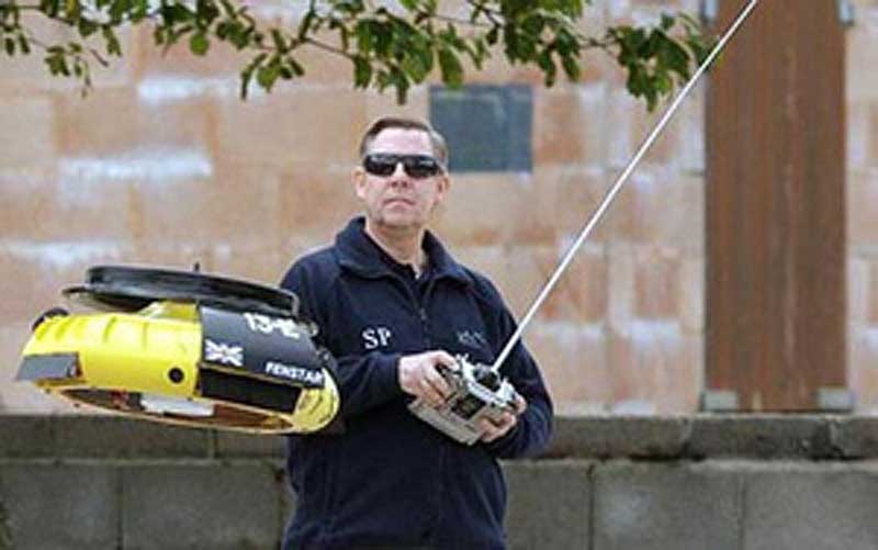
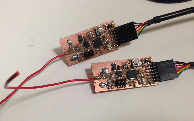
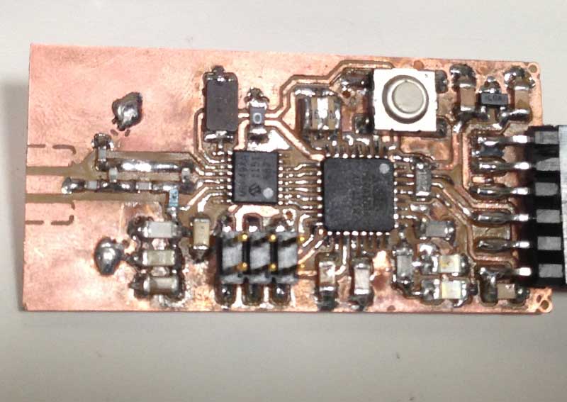
The hello_radio board is a simple digital radio that can send and receeive packets. It is based on a chip called MRF49XA, which is a integrated ISM band RF transreceiver. Within the ISM band, the hello_radio communicates over 434 MHz by default, and uses a original protocol for sending and receiving ascii text. I first started by fabricating the hello_radio board. However, this process was extremely non trivial.
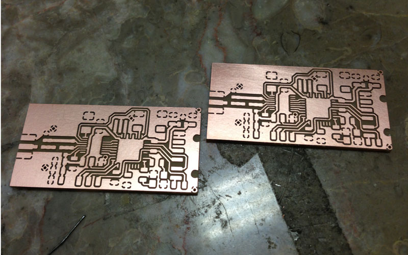
Milling Out the Board
The usual process was to mill out the trace on a PCB using the MODELA. The issue with the hello_radio board was that it contains super thin traces and pads that matches the tiny MRF49XA chip. When I used the following settings which I normally use for milling out traces, the MODELA would tare off some of the pads as it passed by.- Tool Diameter: 0.4 mm
- Z-axis Cut Depth: 0.15 mm
- Machine Speed: 4 mm/s

Thanks to everybody who responded to my email, I figured that the following settings would be better for milling thin traces and tiny pads.
- Tool Diameter: 0.38 mm
- Z-axis Cut Depth: 0.10 mm
- Machine Speed: 3 mm/s
Stuffing the Board
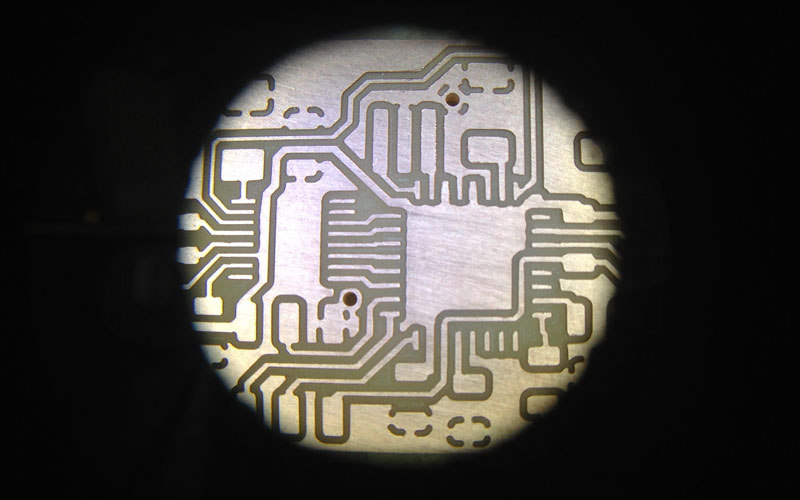
For stuffing the board, I got some advice that a microscope would make the process a lot easier. Thanks to Shaun, he let me use the one in his group.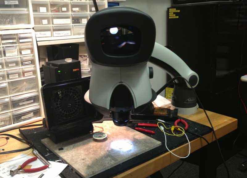
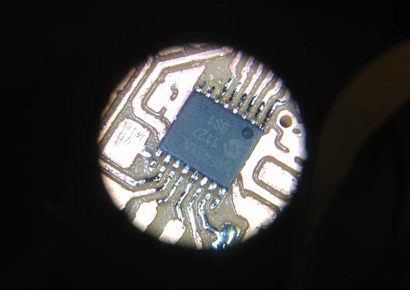
Before stuffing the actual parts, I needed to duburr the edges. Unfortunately, with the new settings, the MODELA was able to leave the tiny pads unharmed. However, edges were terribly dirty. When I tried the normal deburring with the steel ruler, it would either tare the pads away, or leave the dirty edges untouched. After multiple trieds, I took an X-ACTO knife and manually deburred it under the microscope.

After I removed all the particles that could create unwanted bridgs and got nice edges, it was time to stuff the pieces. Thanks to the liquid flux pen and the microscope, soldering ultra small pieces on to the tiny pads were easier than I thought.
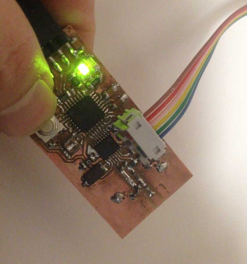
Burning the Firmware
This was the most difficult part of the week. The soldering was pretty straight forward, but when I tried to burn the firmware, it would never work on its first try. I was encountered by the "beauty" of hardware debugging. Fixing bad solder joints and unwanted bridges would make things better. And I managed to burn the firmware on all of the boards, I made, but it was extremely difficult to make a stable board.
Eventually, after remaking the boards four times, I ended up with three unstable boards that sometimes works, one smoked board, and only one board that constantly works. Having one board would not make sense, so I would try to fix at least one more in order to complete my remote controller.
Making Boards That Work (UPDATE)
After the class, Neil pointed out that the all the issues were probably caused by the particals originating from the edges. He also pointed out that bad edges are signs of worn out drill bits. He suggested that I remake the boards with a fresh drill bit. Although I had one board that was functioning, I decided to make a pair of new boards just for the sake of it.The process was straight forward. As soon as I replaced the bit, I noticed significant improvements. The traces had nice clean sharp edges. It was my first time I encountered a board that did not require any deburring.
After stuffing the tiny parts to the two new boards, I burned the firmware on it, and everything worked on my first try. I now had two boards that can talk to each other with digital bits!