Week 14: Machine Design
Overview
The 14th assignment of the semester was to create a machine that can MAKE things. This was the first and only group project of the semester. I worked with Sam Calisch, Catherine D'Ignazio, and Laura Perovich to made the Creepy Crawly Cutter. My main role was to do the electronics. This week, I learned...- The basics of mechanical design
- How stepper motors work
- How to controller stepper motors

Concept
The Creepy Crawly Cutter is a CNC cutting machine that mimics a shapes of a crawling robot. It is equipped with a rotary blade, and has the ability to cut paper or fabric materials as it craws over the surface.My role of this project was to do the electronics. The key point of this role was to control a stepper motor for crawling along the material. At first, everything seemed trivial, but it turned out it was not so simple.
Stepper Motors
Before I did anything, I decided to do a quick survey on how stepper motors work. In short, they are brushless DC electric motors that divides a full rotation into a number of equal steps. The motor's position can then be commanded to move and hold at one of these steps without any feedback sensor.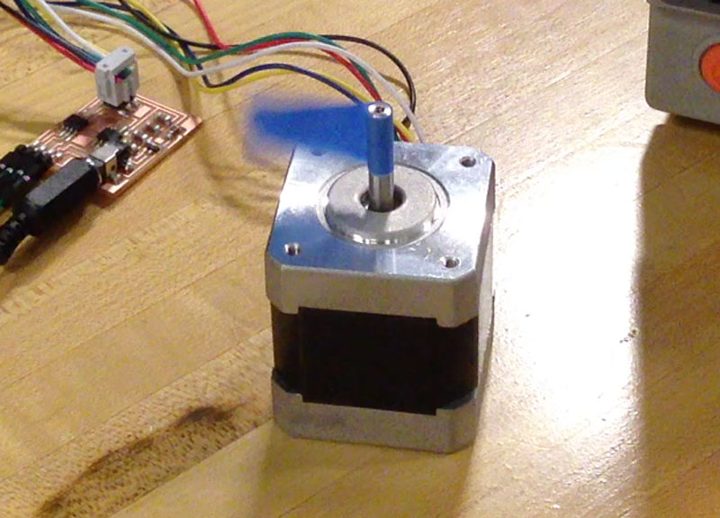
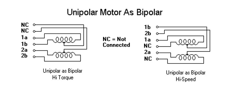
For this week, I used a JAMECO 238538, which is a 6 wire unipolar stepper motor. In order to drive this motor, I first tried to use the Allegro A3967. The A3967 is a integrated motor driver chip for controlling bipolar stepper motors. For controlling unipolar stepper motors with drivers intended for bipolar stepper motors, I learned that I may do so by not wiring the two center taps.
Original Motor Driver
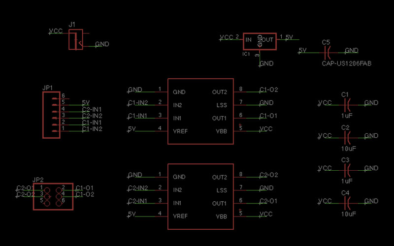
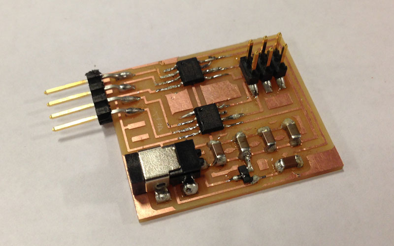
I originally tried to used the A3967 integrated motor driver chip, but Neil advised me that I can easily control bipolar stepper motors with two H-bridges. Therefore, I decided to design and make a motor controller of my own module using two H-bridges. In the circuit, I included an external 12 V power input and a 5 V regulator for powering the H-bridges. I also made it so that it can interface with an external microcontroller.
|
|
Making the Fabduino
As for the processor, I decided to try and make the Fabduino for the second time. For the first attempt during week 11, I couldn't get the Fabduino to work. This time, I used a relatively new drill bit on the MODELA, and milled out the board. The traces came out with a nice clean edge. When stuffing the board, I used the microscope, and within an hour hours, I was able to make a working Fabduino with the bootloader.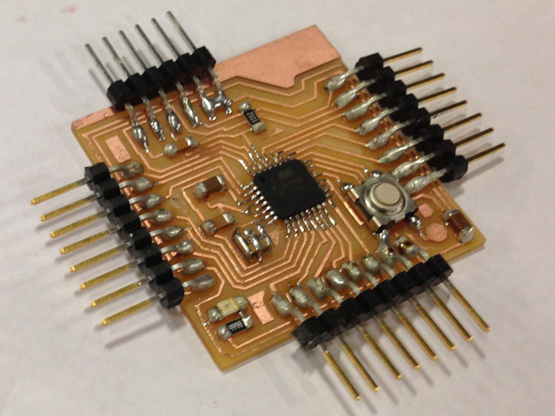
Controlling the Motor
For controlling the motor from a Fabduino, I connected 4 digital output pins to the original motor driver board that I made. I then learned that stepper motors must have as special sequence of pulsed to run properly.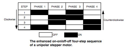
I implemented the code for generating the special sequence of pulses, and was able to control the stepper motor using a Fabduino. One thing I struggled was the current flow of the external 12 V power source. I originally used 200 mA AC adapter, however, I encountered an issue where the motor would skip steps. It took me for a while to notice that the motor draws a current of 400 mA by default. As soon as I attached the driver board to a bench power source, it worked out fine.