Week 11: Output Devices
Overview
The 11th assignment of the semester was to create a output device that does something. I decided to do a recap on the fabrication methods we learned, and combine them towards making a robot base with motors for the final project. This week, I learned how to...- Use the water jet cutter for cutting aluminum
- Cast rubber parts
- Cast plastic parts
- Fabricate the Fabduino board
- Control DC motors with a microcontroller and a H-bridge

For my final project, I am planning to make a robot with a third hand. To move this plan forward, I decided to make a base with wheels and motors for it. I also wanted to do a recap on various fabrication methods, so I decided to make as much parts from raw materials as I could.
The robot base I made for this week has two motors with wheels for moving around. They are controlled by a microcontroller (ATTiny44) board with H-bridges. It also comes with a proximity sensor for automatically detecting obstacles in its way.
I first used the ShopBot for milling out the wood for the base. I then used the water jet cutter for cutting out the motor bracket. I also molded and casted the wheels. And finally, I fabricated the Fabduino board for controlling the robot base. I originally planned to use the Fabduino, but I ran into so much trouble which is described below. So I decided to make a exclusive board with the ATTiny44 microcontroller.
Designing the Base
As usual, I used Solidworks to design the base. Most of the base was made with wood, except for the motor bracket and wheels, which were made with aluminum and plastic.

|

|
|
|
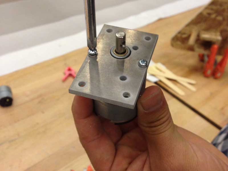
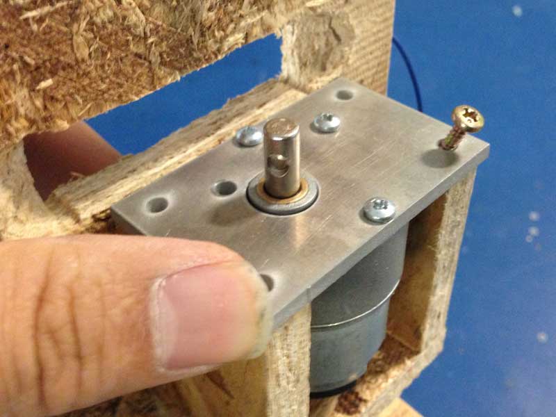
As for the motors, I used the Jameco 253471, which is a 12 volt DC motor with a embedded gear box. I referenced the data sheet to get precise dimensions.

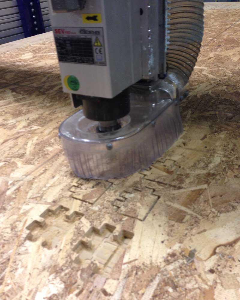
Milling the Wooden Parts
In order to get more experience on the ShopBot, I took a large MDF and milled out the parts. Everything worked fine without any problems. As for the settings, I used the 1/4 inch flat endmill with the suggested preference values.
|
|
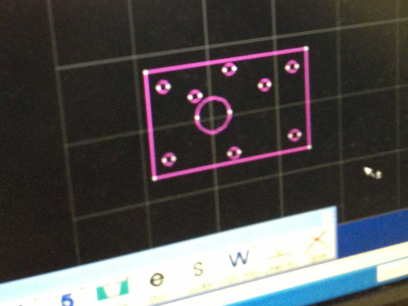
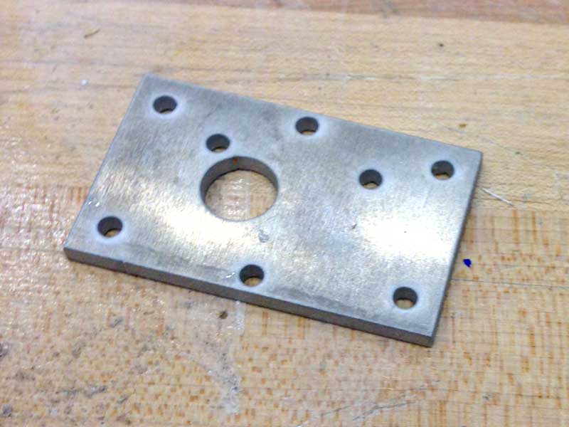
Cutting the Motor Bracket
As I wanted to practice using the water jet cutter, I decided to cut the motor bracket out from a 3 mm aluminum sheet. The process was similar to that of the ShppBot, except the OMAX software had a terrible user interface. The OMAX software does not have a fully automatic toolpath planning feature, so it requires a series of manual operation to correctly set the toolpath.Besides spending extra time getting used to the OMAX software, everything went well without any problems.
|

|
|
|
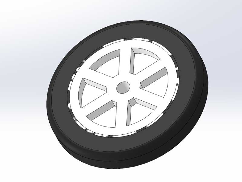
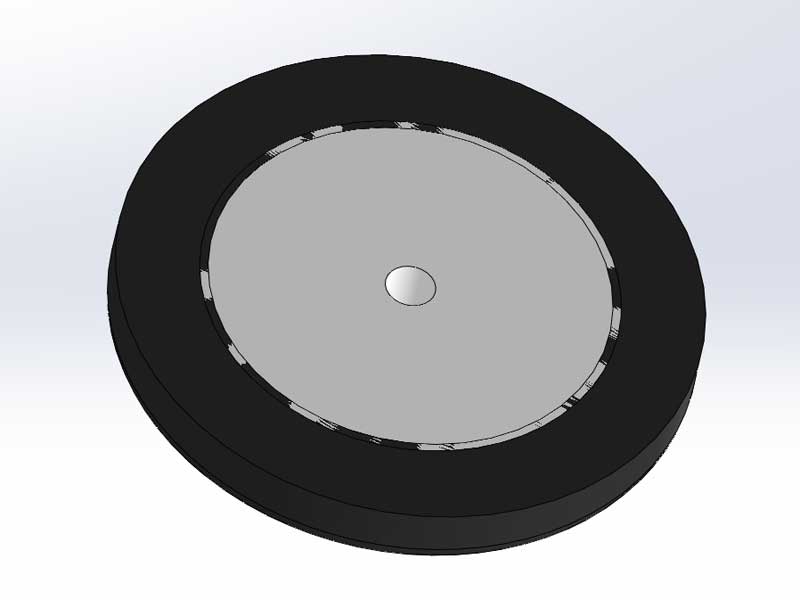
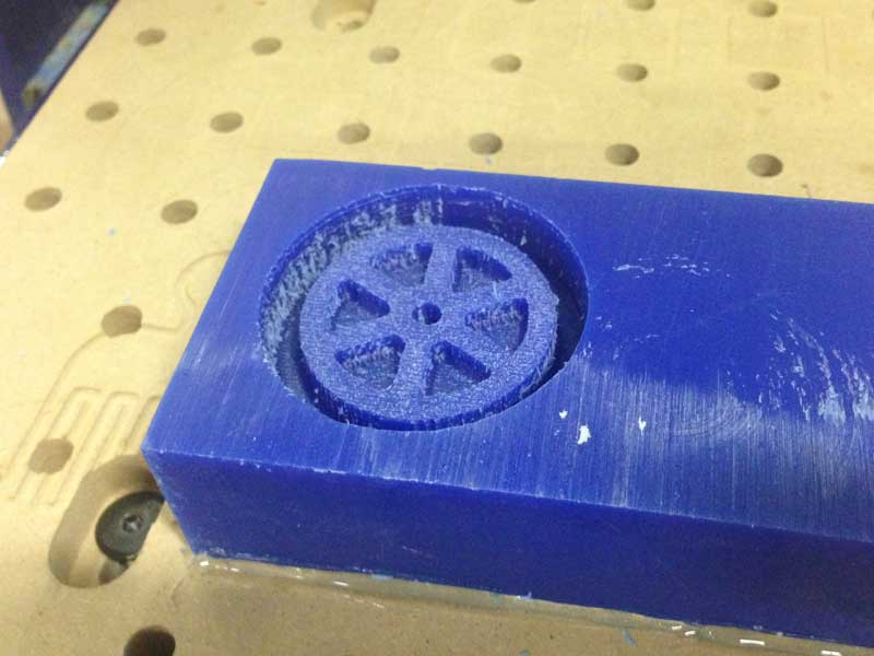
Casting the Wheels and Tires
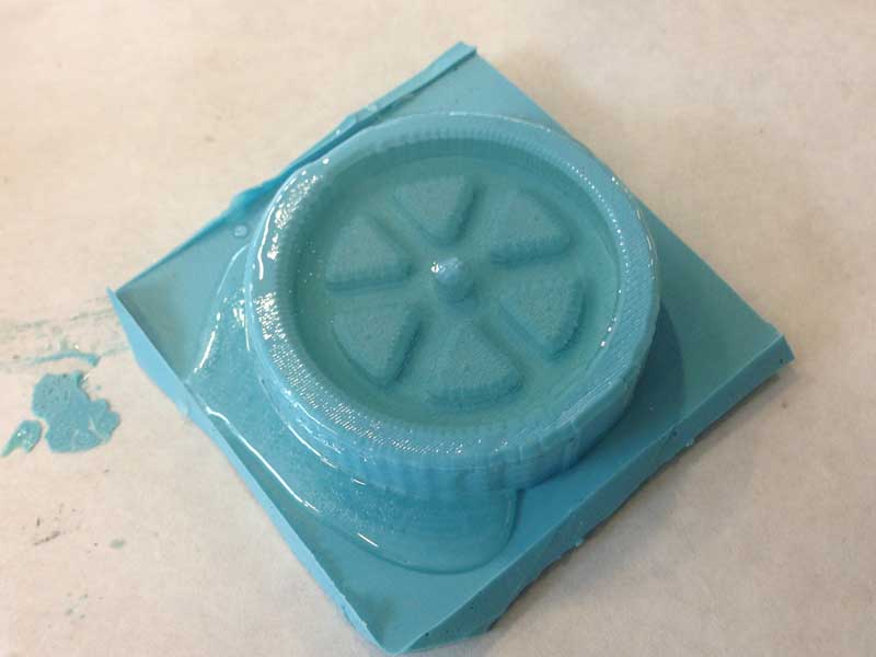
As for the wheels and tires, I decided to create a mold and cast them using liquid plastic resin and silicone rubber. I first exported the Solidworks parts data as STL files, and used the ShopBot Desktop to mill the positive mold from machinable wax. I then used the OOMOO 25 and casted the reverse mold.

|
|

|

|
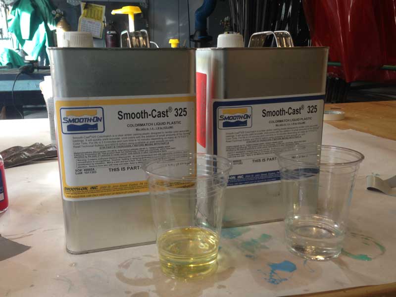
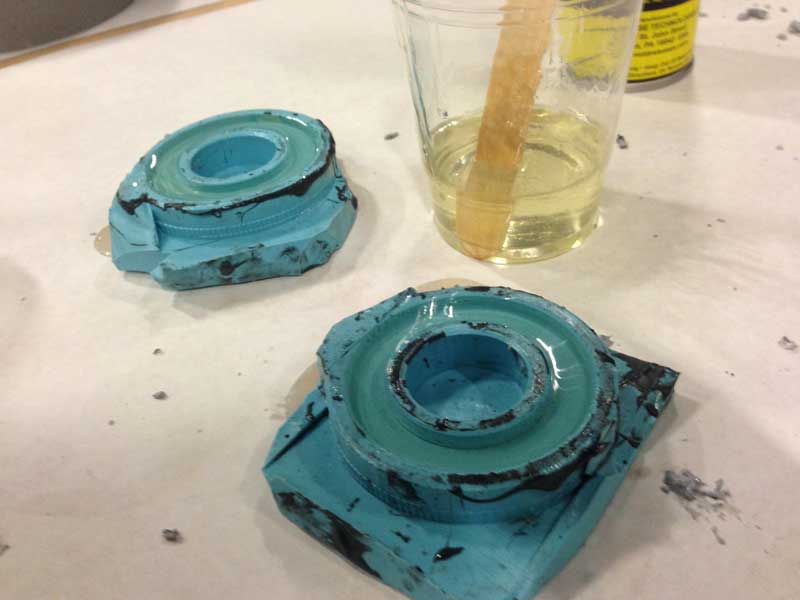
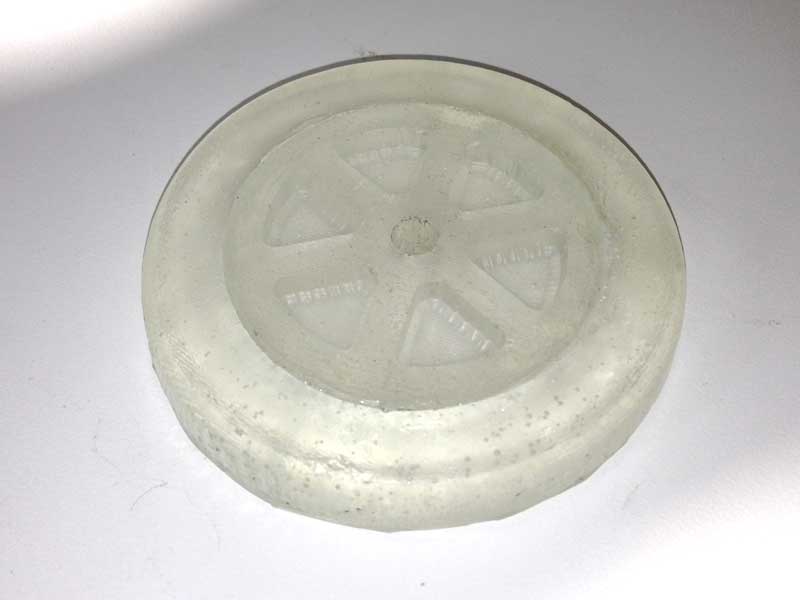
For casting the actual wheels, I used the Smooth-Cast 325 liquid plastic resin. This process was pretty strait forward. After I poured the resin into the reverse mold, it took about 20 minutes to cure and set.
|
|
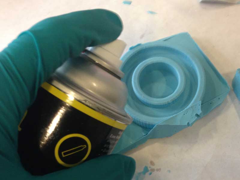
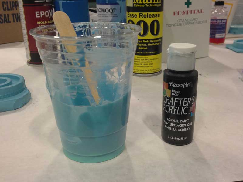
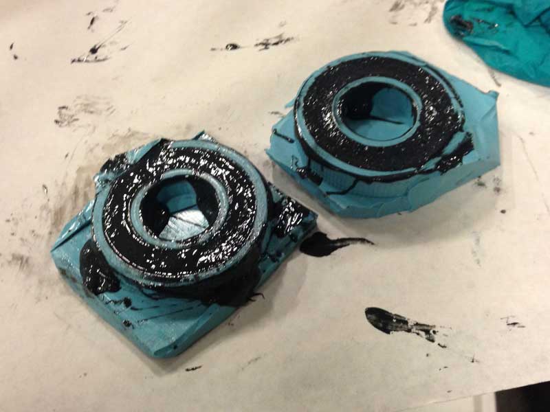
For casting the tires, I first used the OOMOO 25. Before starting the casting process, I sprayed the remover on the reverse mold. I then added some black acrylic paint into the compound to apply some color. Everything worked fine, but when I tried to attach the tires onto the wheels, none of the adhesives worked. So I decided to take another approach.
|
|
|
|
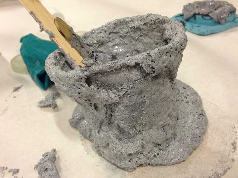
As for the second try, I decided to use the Smooth-Cast 325, which is the same material I used for casting the wheels. Before pouring in the resin, I added the same black acrylic paint to apply some color. However, after a few moments of mixing, the resin started to boil up and "exploded" like a volcano.

|
|
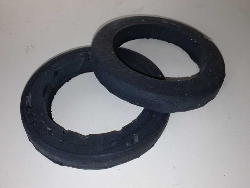
After two failures, I decided to use plain plastic resin for the tire, and attached the tires to the wheels with epoxy adhesive.
|
|
Fabricating the Controller Board
The next step was to create a controller board that drives the motors accordingly to the proximity sensor values. I decided to used the Fabduino board for this. In addition to the main page for the Fabduino board, I consulted Tiffany's website from last year to get detailed tips for the process.The fabrication process was strait forward. However, I wasn't able to burn the bootloader on the board. Apparently, the Fabduino board had so many thin traces and small gaps which made it extremely easy to create shorts within the circuit. I managed to fix a few shorts, but I was sure there was more that I wasn't able to find.
|

|
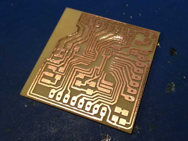
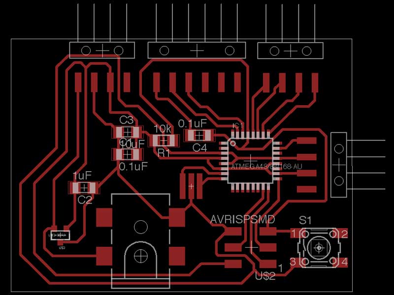
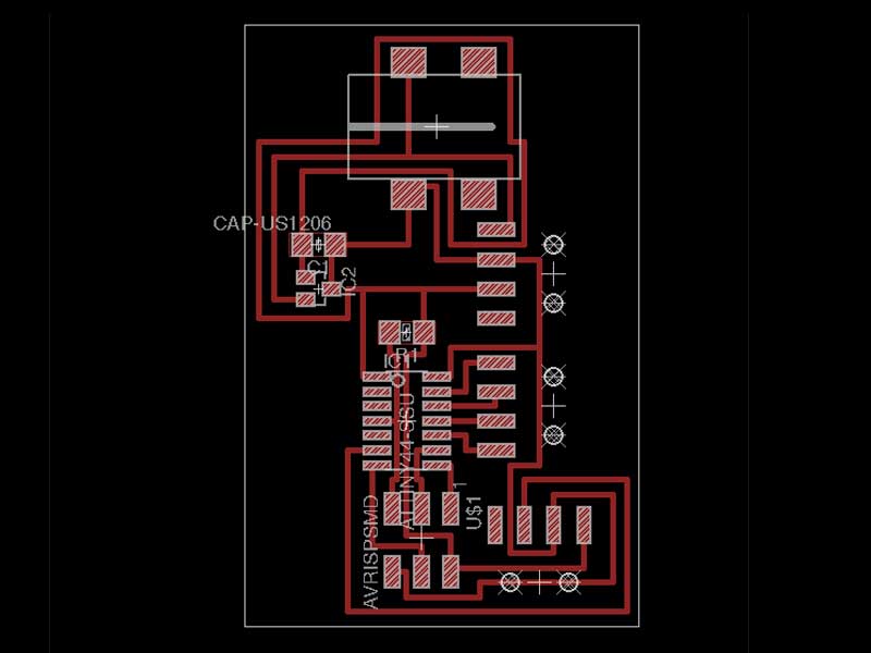
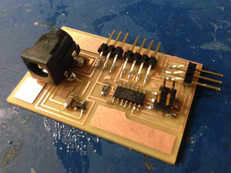
So instead of debugging the board, I decided to create my own version of the fabduino with the minimum amount of traces from the pins. I also added a voltage regulator to enable the usage of a 9 volt battery, and ISP header pins to make it easy to program the board.
|
|
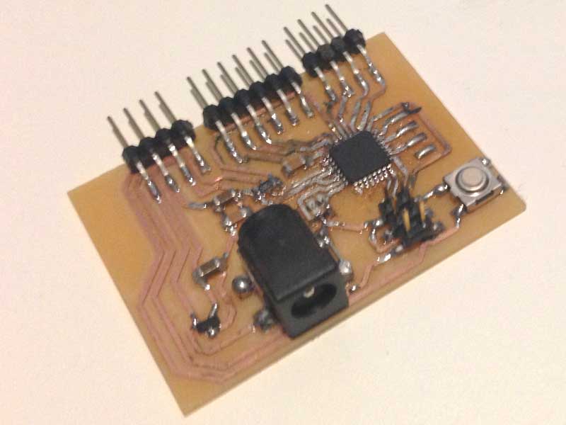
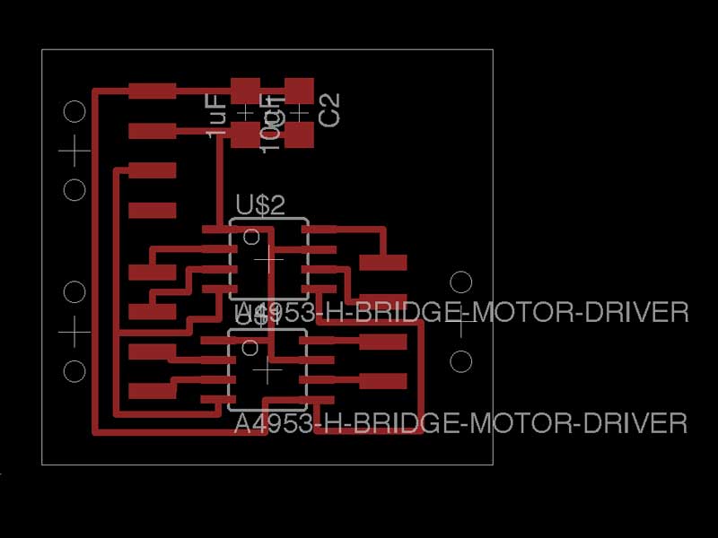
I milled the board and stuffed it, but I was still having trouble burning the bootloader. After a few hours of trying to debug, I gave up and decided to make a new board by modifiying Neil's simple motor contorller board with the ATTiny44 microcontroller. Upon modifying the board, I decided to separate the H-bridges (1 for each motor) for future integration with the Fabduino. As for the H-bridges, I used the Allegro A4953.
|
|
|
|
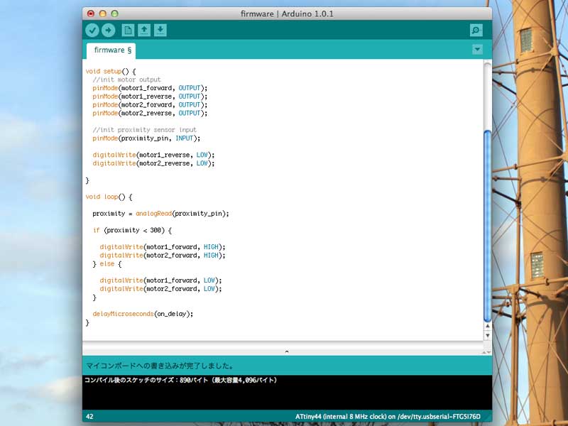
Programming the Controller Board
For programming the board, I used the Arduino software. To make things simple, I made the both of the motors to go forward constantly as long as there is no obstacle blocking its way.For detecting obstacles, I used the SHARP GP2D12 IR-based proximity sensor. According to the datasheet, it outputs a voltage between 0 and 3 V, depending on the distance to the reflective material. In the control loop, I used the analog input for reading the sensor values, and made it so that it stops the motors when there is something within 20 cm from the sensor.
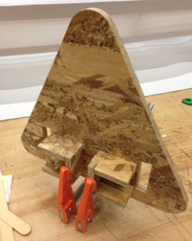
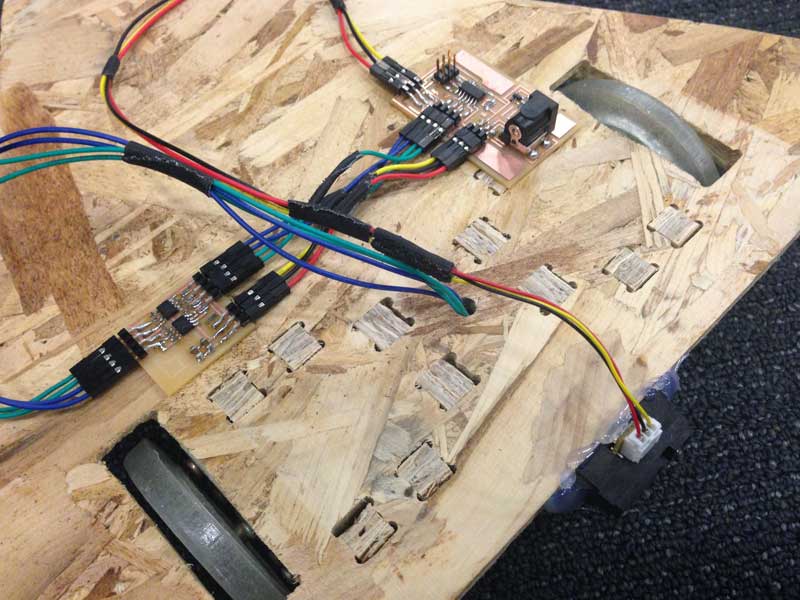
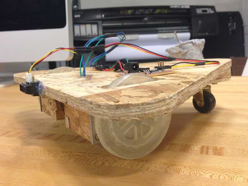
Integrating the Parts Together
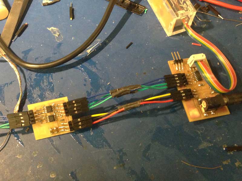
Assembling the body, motors, wheels, controller boards, and wires together was the most exciting part. I also attached a bearing caster on the rear to balance the base.
|

|
|
|
After everything was done, I connected a 9 V battery to the board and tested the robot base. Unfortunately, something was wrong with the motor drivers. It seemed a constant voltage was not being fed into both of the motors. Therefore, the robot base moved in a awkward way, but the control loop with the proximity sensor was working. I would like to work on debugging this issue towards the next few weeks.