Week 5: Electronics Design
Overview
The 5th assignment of the semester was to redraw the "Echo Hello World" board using EAGLE. We were also required to add some input and output components, such as a switch and a LED, to the board. This week I made the "FTDI.io" board, and learned...- The basics of electronics
- How to use EAGLE
- Design and produce my own electronic circuit
Redrawing The Original "Echo Hello World" Board
The original "Echo Hello World" board is a very simple circuit board with an ATTiny44 microcontroller, external 20 MHz oscillator, and FTDI pin headers.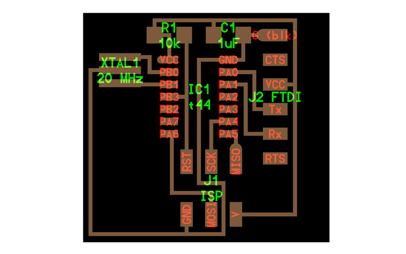
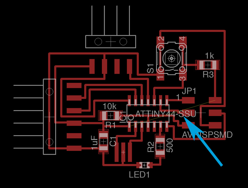
In order to fullfil the requirements, I added a switch (with a 100K Ohm pull-up resistor) for an input, a red LED (with a 500 Ohm resistor) for an output, and pin headers for an external sensor with analog input on my FTDI.io board. I redrew the schematics using EAGLE, which is a software tool for designing circuit boards. It was kind of hard to get used to its interesting UI, but I was able to get on track after practicing for a couple of hours. As for the parts, I mainly used the FAB Parts Library and the SparkFun Parts Library.

After I got the schematics in place, there came the process of creating the layout of the actual circuit. This turned out to be the most complicated and time-consuming step of the week.
I first place the components so that relavant pads are more or less close to each other.
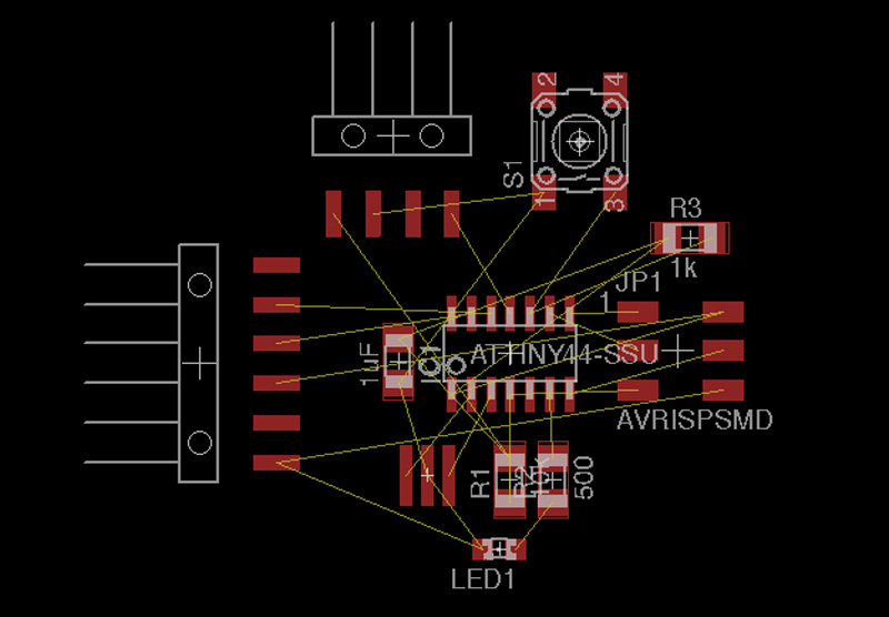
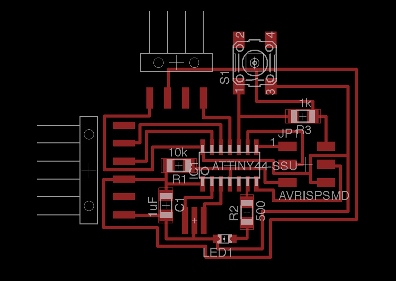
I then connected the pads with "routes". However, this was like solving a complicated graph topology. It would work relatively fine at first, but I always ended up with extra routes that cannot be connected without over lapping other routes.
There is always the work-around of bridging the circuit using a 0 Ohm resister, but I didn't wan't to give up soving my puzzle, and finally came up with a solution after a long fight with EAGLE.
After I was successful in creating all routes, I ran the DRC check to make sure my circuit was OK. It pointed out that some of the routes were in conflict with the components.
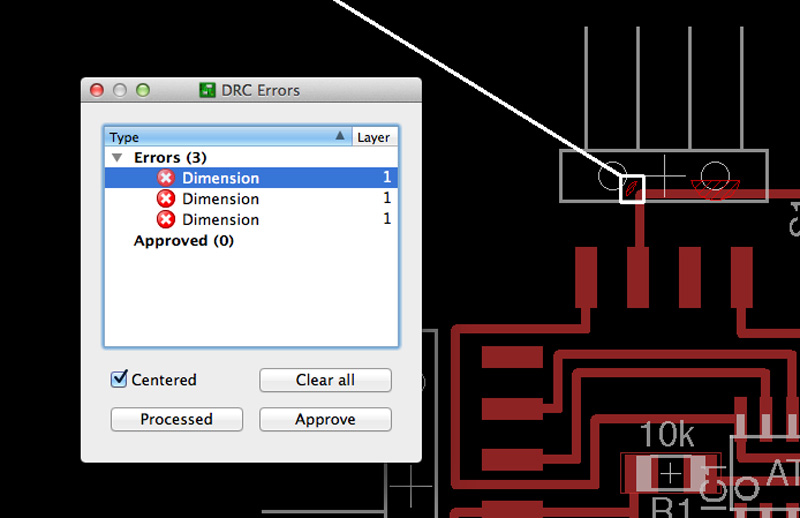
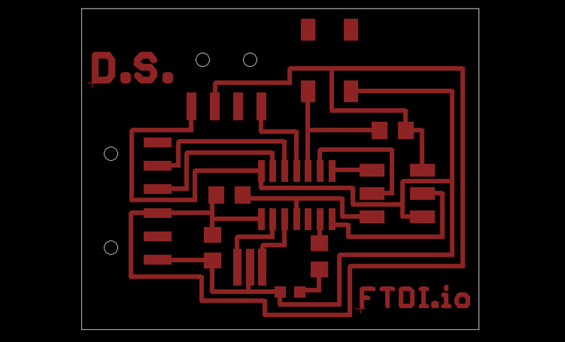
I rerouted the problematic portions of the circuit and was finally able to get a nice complete circuit trace no bridges. I also added my initials and the title of my board ("FTDI.io") in the traces, and exported as a PNG file with a 1500 dpi resolution. The traces and the board outline file may be downloaded below, along with EAGLE files.
Milling the PCB
For milling out the circuit board, I used the MODELA with Fab Modules. Thanks to all the lessons I learned during week 3, I was able to mill out the board successfully on my first try. (I've definately gotten better at this...)Stuffing the Circuit
The stuffing process went smooth as well. I first mounted a small drop of solder on to a single pad for each component, and used it to hold the parts in place. I then went back and soldered all the pads.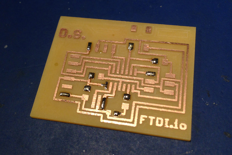
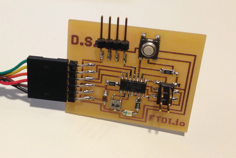
After stuffing all the parts, I had my very own FTDI.io board!

Programming the Board
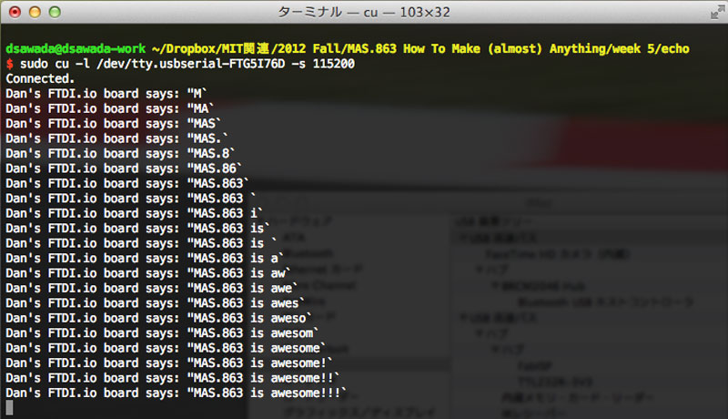
As for extra credit, I programmed the board using the FabISP I made for week 3. I modified the original echo.c program, and made it so that it outputs a carrige return code (ascii code:10) after each line output. I also modified the Makefile for making the build process easy. You can download the source files below.After modifiying the code and successfully compling it, I burned the HEX file onto the chip, opened the virtual serial port of the FTDI interface using the cu command, and verified the program works.
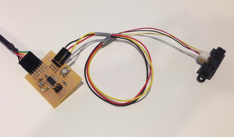
I didn't code anything for testing the input and output functions for this week, but I hope to try this out in the comming weeks. The following image shows my FTDI.io board with a proximity sensor connected to the analog input interface.