Week 9: Input Devices
Overview
The 9th assignment of the semester was to create an input device and make it sense something. As mentioned in the final project proposal, I want to make a third hand robot that can remotely sense the stiffness of an object. This week, I decided to make an artificial "fingertip" of my third hand that functions as a sensor to measure the stiffness. This week, I learned how to...- Use the capasitive step response sensing technique
- Use the hall effect sensor
|

|
Approach
For sensing the stiffness of an arbitrary object, I figured it would be possible by using a compression spring. In theory, when hard objects are probed, the spring would get pushed back more, as where when softer objects are probed, the spring would get pushed back less.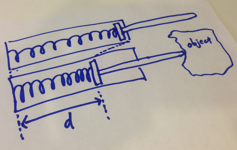
The next question would be to figure out how to detect how much the spring is getting pushed back. There are couple of ways of doing this, so I decided to try out some of them and find out what is the most feasible.
Hall Effect Sensor
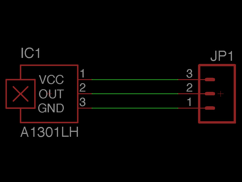
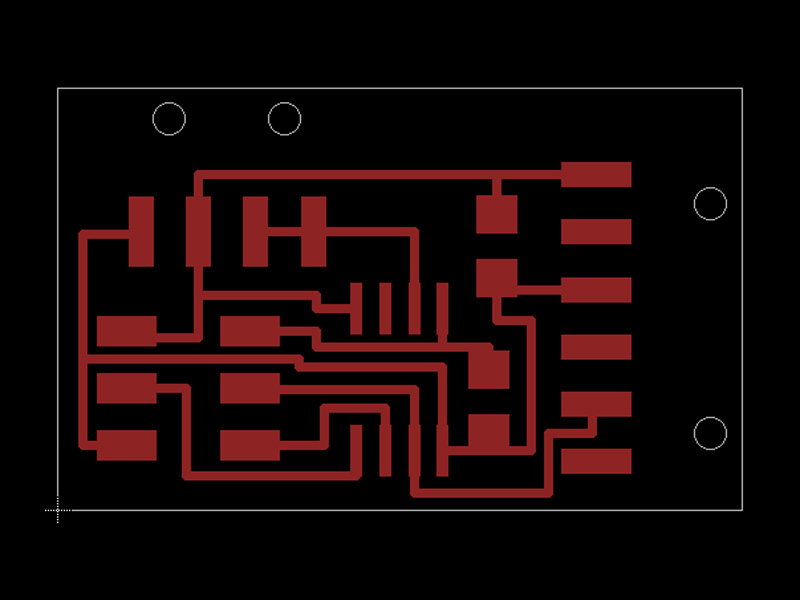
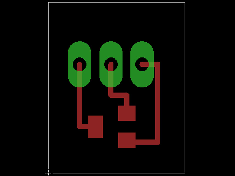
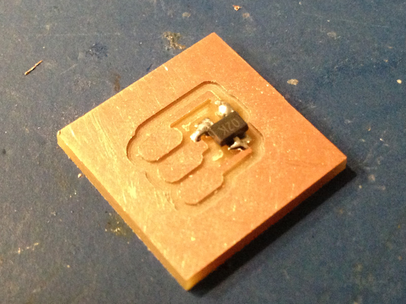
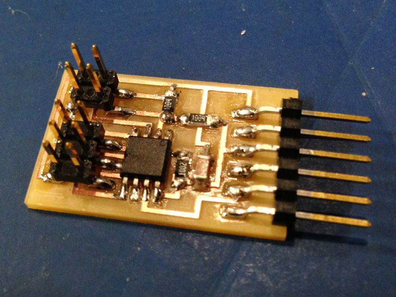
I first tried to use the hall effect sensor to measure the length of the compression spring when objects are being probed. Since there was no reference board within the class web site, I designed and created my own.As usual, I used EAGLE to design the board. I also used the MODELA to mill out the traces. The schematics and trace files may be downloaded below. Upon designing the board, I separated the sensor unit from the controller in order to make it easier to place the sensor to any desired location.

|
|
|
|
|
|
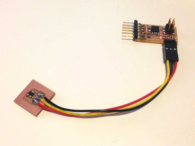
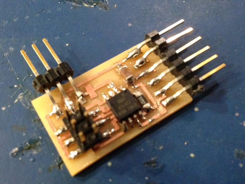
After the board was complete, I programmed the board so it sends out ADC readings to the serial interface. When I tested it out to see if worked. Luckily, the board was fully functional. However, I soon realized that the hall effect sensor would not be feasible for measuring the length of the spring.
As shown below, the given hall effect sensor within the class inventory (A1302KLHLT-T) was not capable of sensing the magnet more than few centimeters away. In addition, the sensor readings were not proportional to the distance between the magnet and the sensor.
Therefore, I chose to take a different approach, and use capasitive step response sensing technique instead.
Capacitive Step Response Sensing Technique
As for the second approach, I used the capacitive step response sensing technique. It didn't take long before I realized that this is a very simple, yet extremely useful method of measuring the distance between two given points in a linear way.To begin with, I took Neil's reference board design (Hello TX/RX Board) and milled out the traces using the MODELA.

|
|
After I fabricated the board, I programmed the board with Neil's reference code (hello.txrx.45.c). This program sends out the capacitance readings to the serial interface. I then connected 2 pieces of copper to the TX and RX pins and examined the readings. As the overlapping portions increased, the sensor readings also increased proportionally.
Designing the Enclosure
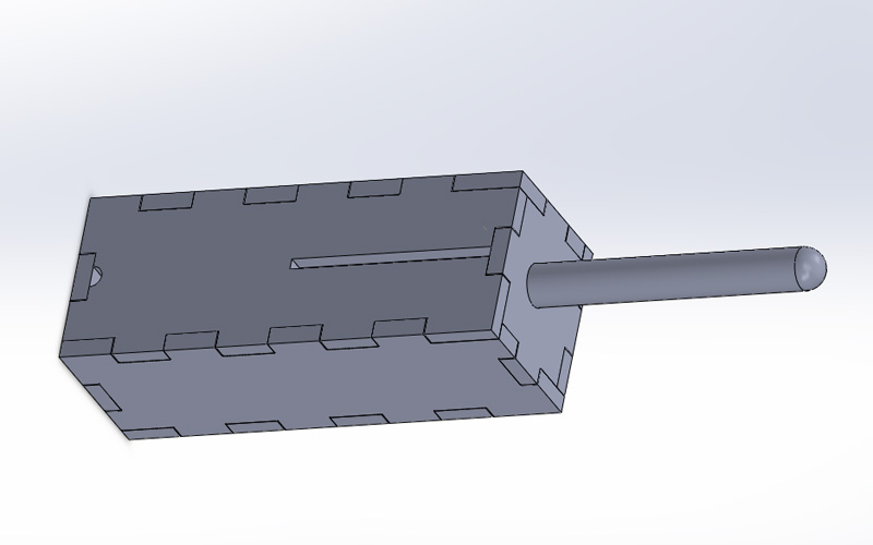
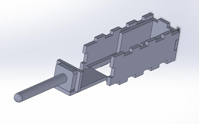
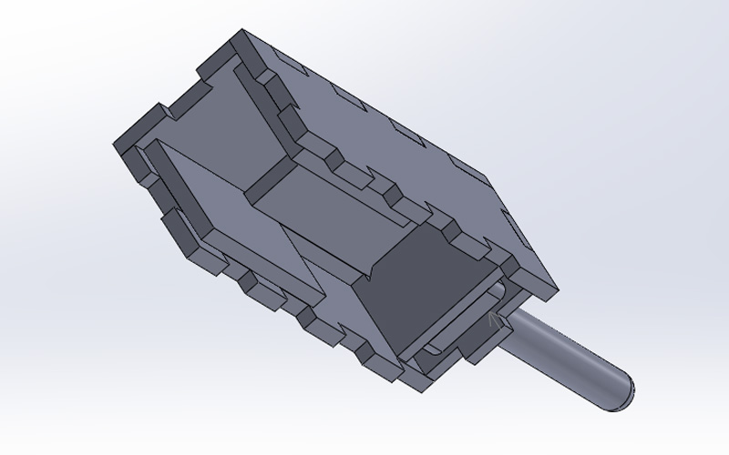
Now that I had the sensing mechanism, I decided to design a enclosure for my stiffness sensor. I opened up solidwoks, and designed a press-fit acrylic eclosure with a 3D printed "fingertip" probe. The design files may be downloaded below.
|

|
|
|
I also ran to the hardware store to buy a suitable compression spring for my sensor. After looking through, I ended up bying the following spring.
- Diameter: 0.625 inch
- Length: 2.75 inch
- Spring Constant: 0.041 WG

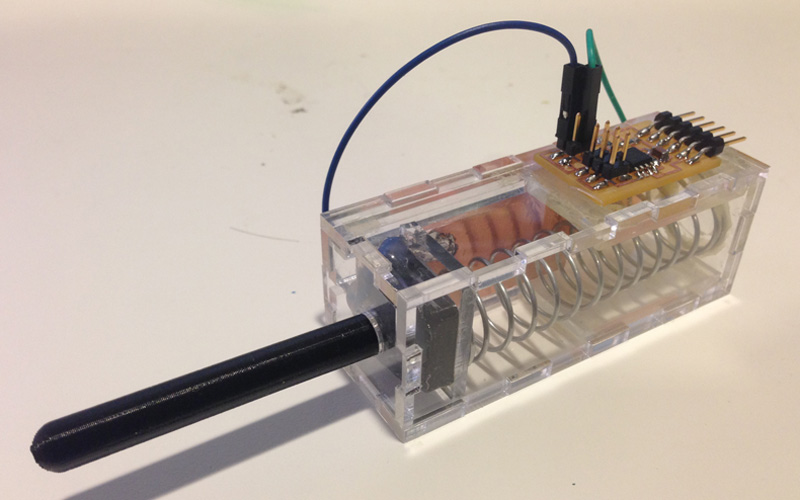
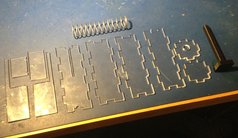
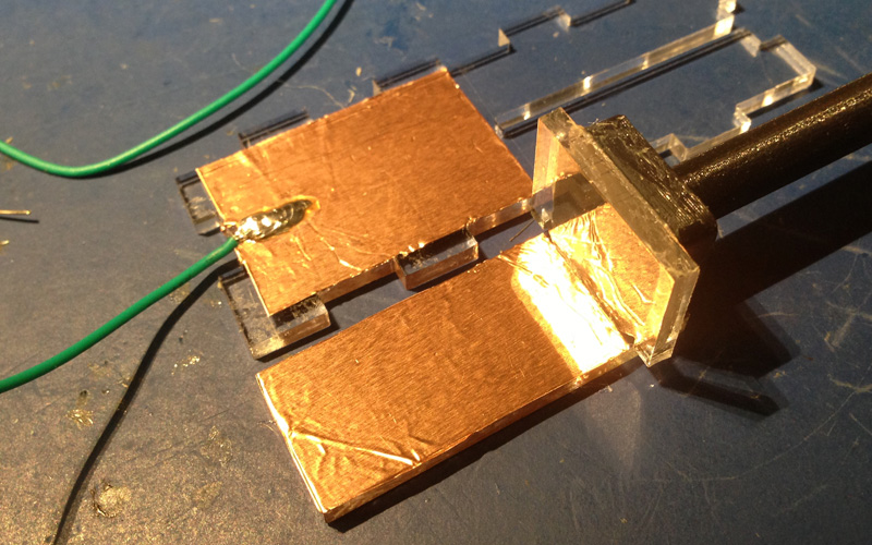
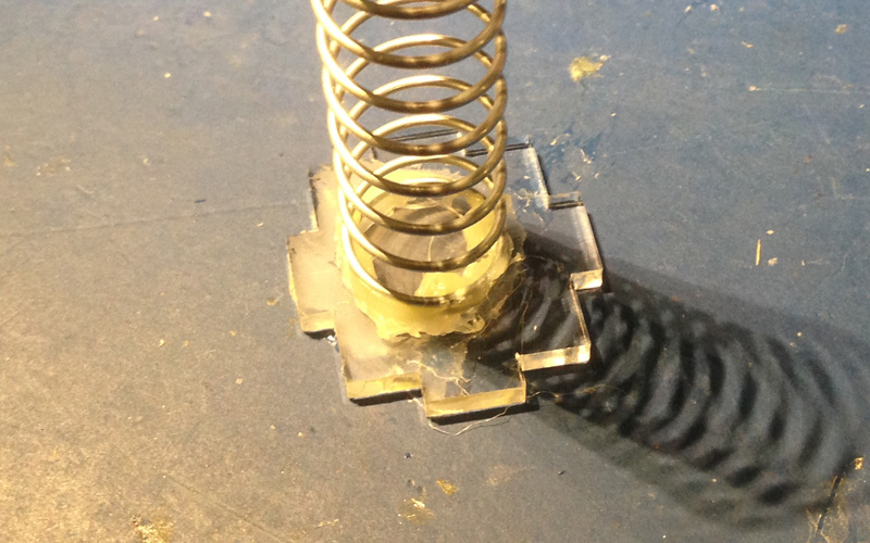
After I laser-cut the parts from a 1/8 inch acrylic board and 3D printed the "fingertip" probe, it was time to put everything together. For the two conductive parts for capacitive sensing, I put some copper tape on to some portions of the acrylic parts and led wires. In order to make the structure more stable, I also applied some epoxy adhesive on certain joints.
|
|
|

|
After everything was done, I connected the FTDI pins to my FTDI cable, and verified everything works as planned.