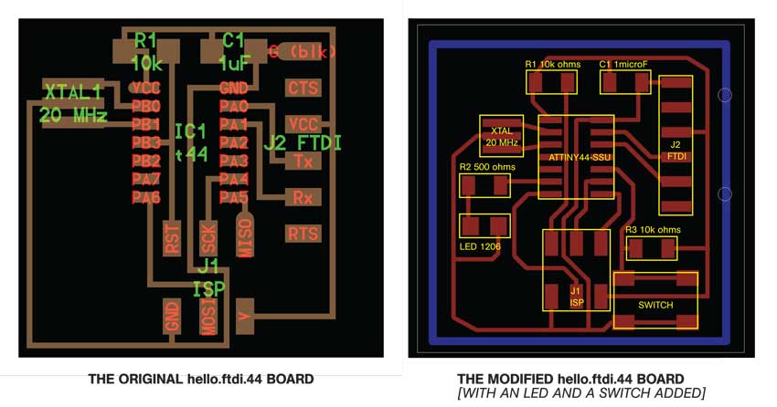
hello.ftdi.44 Board Modified
As always, we alternate between making actual things [fabrication] with electronic assignments, which I'm a novice in. This time, we were asked to re-draw the hello.ftdi.44 board, and add a switch and an LED light on it. I learnt how to use the Eagle software to draw the board. I then milled and cut the board together with my studiomate, Chris Malcolm , at the Architecture FabLab's Modela machine.
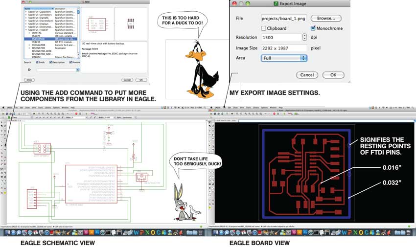
Eagle Software Interface
Using Eagle software to draw the schematic of the board. The software helps you to sketch the components in a loose way, and at the same time allow you to generate the .png files to be sent to the Modela.
Here I used 0.016" as the routing lineweight, and 0.032" for the cut perimeter line.
A few notes: 1. Both Schematic and Board views always have to be open all the times.
2. If you close one of them, the link between the two will be, sadly, broken.
1. Make sure to switch off the other layers you're not using, to export the correct images.
2. Choose the monochrome box to get perfect BW .png images.
3. Bring the resolution up to 1500 dpi.
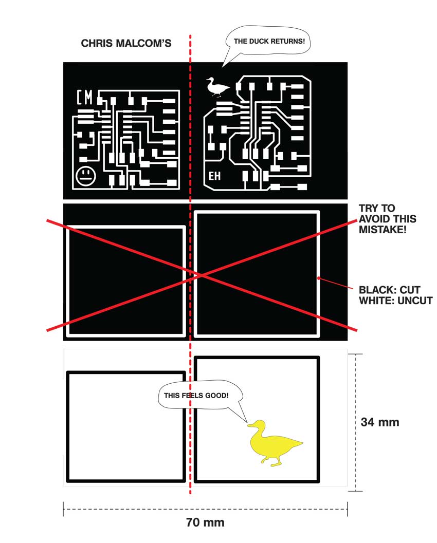
PNG Images for Trace and Board Modela Cuts
I used the FabModule software installed at the Architecture FABLab to create the toolpaths for modela. Innitialy, the images were not recognised, and I noticed that:
1. The images should be on RGB, not Index, format. I fixed this using Gimp -- very easy and handy program to have.
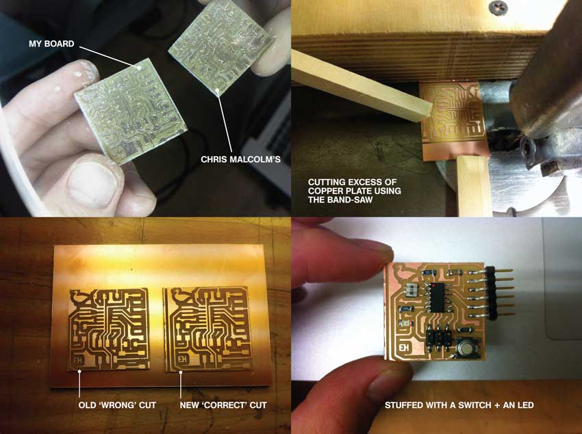
2. I made a mistake with the cut file .png image that I sent. It had the cut line as white, whereas it should have been the inverse, i.e. black, as the end-mill cuts the black, not the white portion of the image.
As a result, the first board I did was left with only a tiny bit of copper connections, which could easily be removed by scratching on the surface. I decided to cut for the second time -- with the inversed image, of course.
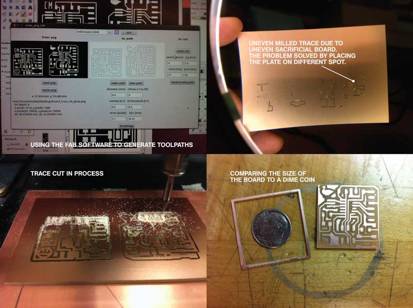
Milling Process 1
Going through the milling process often involves trial and errors. One common problem IŐve encountered is the unevenness of the sacrificial board, which results in uneven trace cut.
I did:
1. Put enough double-sided sticky tape to ensure the plate is flat.
2. Add the depth of trace cut to -0.125 mm and kept the outline cut -1.65 mm.
3. Debur the board gently with a metal ruler.
Milling Process 2
Stuffing the board was not too hard, although you want to make sure the ATtiny44 microcontroller and the LED [anode is marked with a line] are oriented correctly. I only realised later that I had cut the board way too small that the FTDI pins don't have support to rest on the board. Make sure to count for the space for this 6 pins on your board.
Next, I want to:
1. Have more fun with the shape and placements of components on the board -- this is my first time drawing an electronic circuit in a software.
2. Program the microcontroller to perform a few different functions.
3. Be more electronics-savvy. What else would you want?