Machining is any of various processes in which a piece of raw material is cut into a desired final shape and size by a controlled material-removal process. The many processes that have this common theme, controlled material removal, are today collectively known as subtractive manufacturing, in distinction from processes of controlled material addition, which are known as additive manufacturing.
An industrial robot is defined by ISO as an automatically controlled, reprogrammable, multipurpose manipulator programed in three or more axes. The field of robotics may be more practically defined as the study, design and use of robot systems for manufacturing (a top-level definition relying on the prior definition of robot). Typical applications of robots include welding, painting, assembly, pick and place (such as packaging, palletizing and SMT), product inspection, and testing; all accomplished with high endurance, speed, and precision.
Simple shelf test. For this machinig test I played with the tool and toolpath geometric characteristics to produce 3d textures on a 1.5 inch thick piece of plywood. Also milled 2d slots and pockets for the shelfs to fit together.
 |
 |
 |
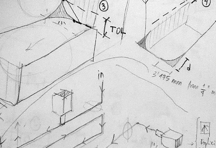
Sketching the toolpath geometry. |
Kuka HA-100 Robot performing 3D cuts. |
First finish texture pass (1/2 inch ball mill). |
 |
 |
 |
Finished textures (1/4 & 1/2 inch ball mill). |
Assembled test. |
Lessons learned. |
First lessons learned: don't step down but drill the press fit dog bones, use short vacuum pucks to avoid vibration, and perform a contour cut of the stock to make sure it is straight.
For this next iteration of the shelving unit we teamed up with Cagri and Guillermo and learned from the previous experience.
 |
 |
 |
Sketching the toolpath geometry. |
Figuring out the changes in the design. |
Producing a new 3d path geometry. |
 |
 |
 |
Milling (1/2 & 1 inch end mills) in the top side. |
||
 |
 |
 |
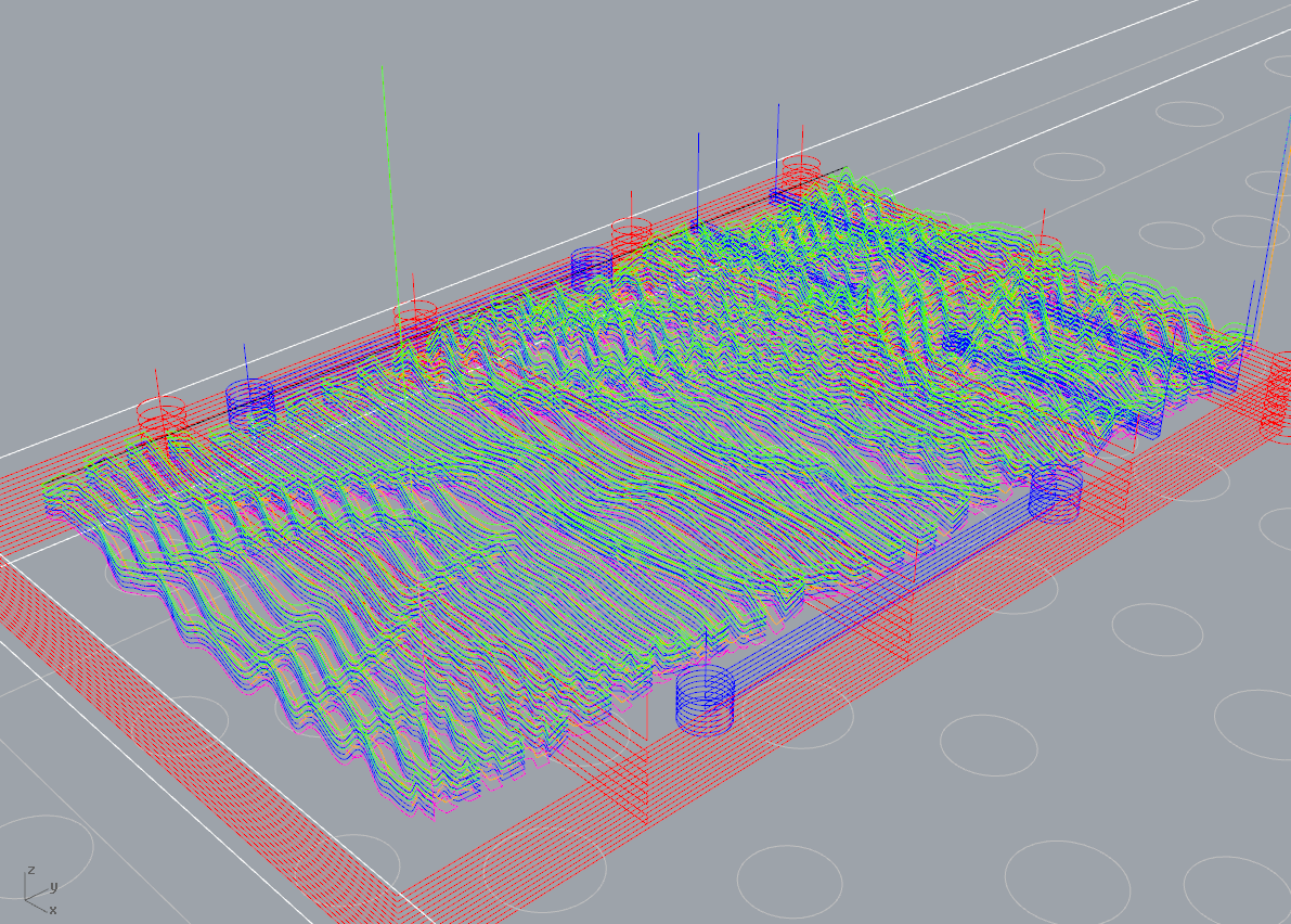
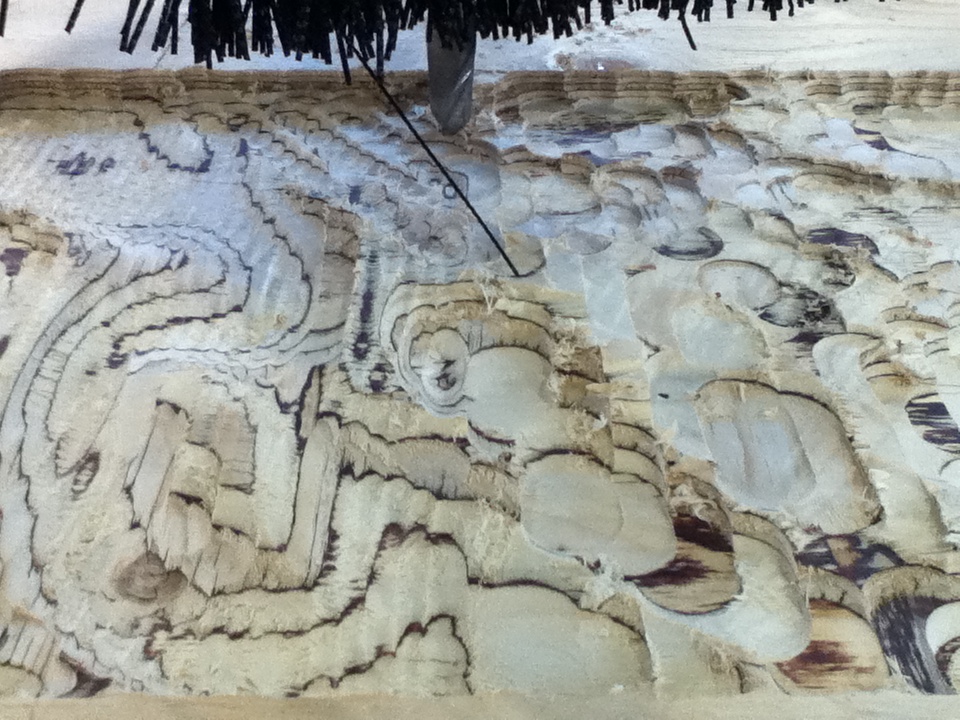
3D rough pass with a 1 inch end mill. |
Path geometry for the flip side. |
Finishing and cut out paths. |
 |
 |
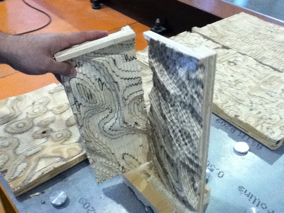 |
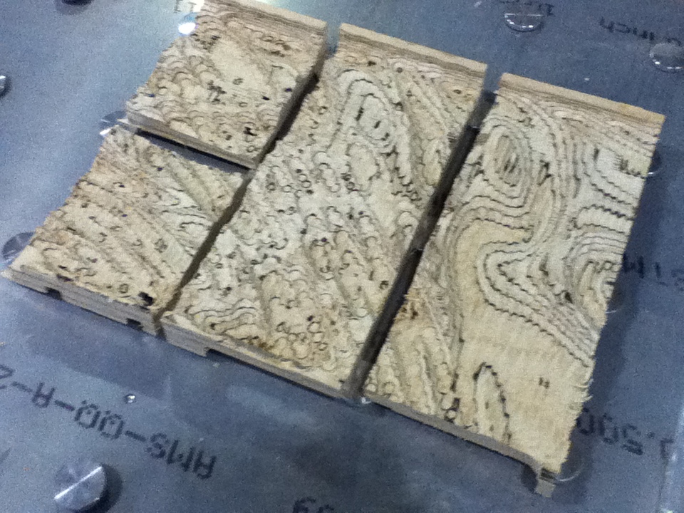
Finishing pass with a 1/2 inch ball mill. |
Cut out pieces with a 1 inch end mill. |
Joint tests. |
A water jet cutter, also known as a waterjet,[1] is a tool capable of slicing into metal or other materials (such as granite) using a jet of water at high velocity and pressure, or a mixture of water and an abrasive substance. The process is essentially the same as water erosion found in nature but greatly accelerated and concentrated. It is often used during fabrication or manufacture of parts for machinery and other devices. It is the preferred method when the materials being cut are sensitive to the high temperatures generated by other methods. It has found applications in a diverse number of industries from mining to aerospace where it is used for operations such as cutting, shaping, carving, and reaming.
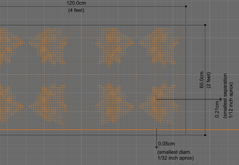
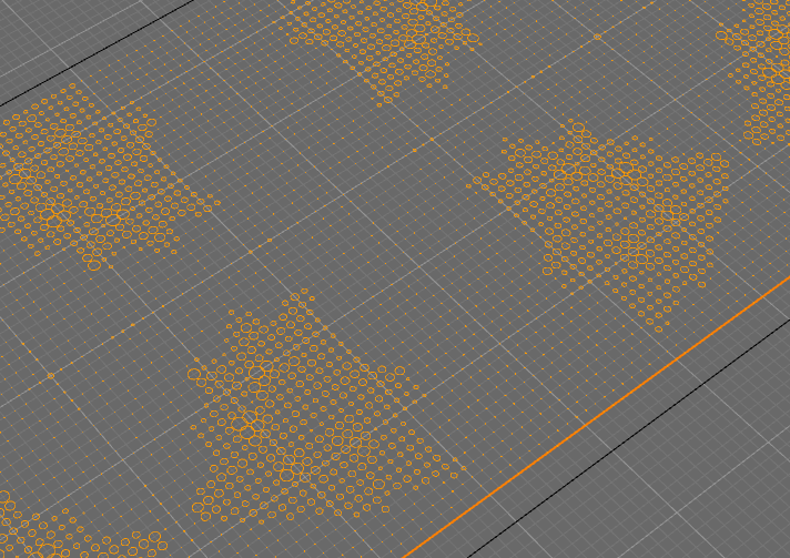
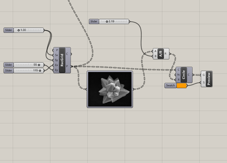
For this water jet test I produced a very simple file that arrenges many circles on a 2x4 feet saluminium surface. The arrangement corresponds to a rectangular grid of the image sampling of a pollen picture taken with a microscope. The machining with the Omax water jet is not completed yet...
 |
 |
 |
CAD file dimensions. |
Geometry close up. |
Simple definition. |