2012 How to Make almost Anything
PCB & FAB ASSEMBLY
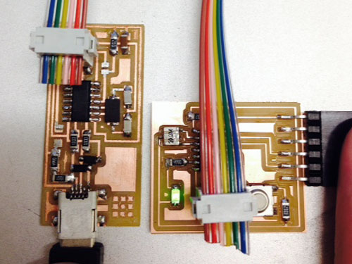

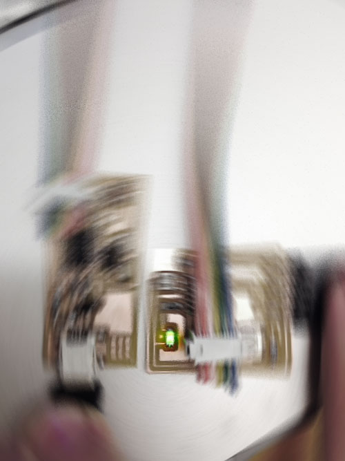
My original board had; at least; the following problems:
Switched led. The cathode should be pointing away from the microporcessor, not toward.
The FTDI connector was puched forward too far in the board. The trace of the component was not shown in Eagle, when i was designing the board so i did not know that it should have been placed closer to edge. This caused the metal pins to be in contact with another trace on the board.
I was not expecting the FTDI cable to be so tight on the FTDI pins. This added with the fact that my baord had the pins pushed too far into the baord made the copper pads peel off from the board. I was having a nightmare of a time trying to debug my original board as it were so a new board was not that terrible of a concept. I was getting pretty adept at using the modela through the weeks. Also note, that as cool as really wavy traces look when designing the PCB, it makes it very hard to trace your components back through the board.
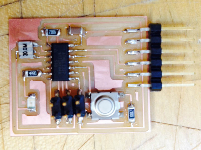
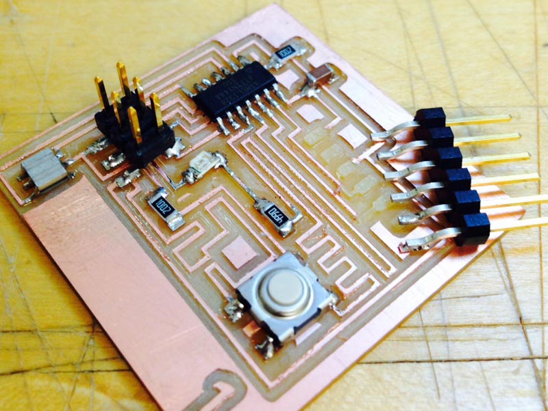
After seeing my classmates move throught the last electonics assignmenta I had many resources to look at when redesigning my board. In order to minimize the variable of debuggin later on, I stuck very close to this tutorial.
Keep in mind that the button is not completely unorientable. It has tow distinct sides. the gate through the button is located only on two sides so it has 90 degrees of error. Also as you are learnign to solder make sure that you start soldering your FTDI pin on an empty pad first just in case you accidentaly pull up a pin when trying to elevate the pins enough so they dont touch any of your other traces.
In another attempt at removing the variables I decided to use Arduino first. My reasoning was, if the environment was as easy as everyone said, then if i couldnt get it to work then there must be something wrong with my board. And since my board design was a tried a true mehtod, then I knew it had to do with the components on the board, mainly the soldering. LUCKY enough i did not have to run through this rigourous debugging process with my new board. Almost immediately after following a very straight forward tutorial on programming the attiny with arduino and running a test blink command my light turned on.
With a little stiching of example codes and a small random function I created a code that when the button was pressed the light would turn on with a slight delay, and then with the button unpressed the light would turn off with a different delay.
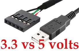
NOTE: the internal 8mhz clock inside the processor will work fine at below 5 volts from the FTDI cable, but when switching to an external resonator at 20mhz, make sure that you are using a 5volt FTDI cable. you will recieve a not in sync error when trying to burn to bootloader in arduino.
After moving through arduino with sucess I went on to try C language and get my light to turn on through it.
The tutorial I followed can be found at this site on the fab server.
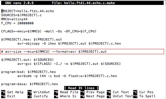
While creating the hex file I immediately encountered and error 1 in the avrdude size. The TA explained to me that this error was due to versions of various software in conflict with one another and was random error that could not predicted. More importantly he fixed by simply commenting out the avr dude size line in the file hello.ftdi.44.echo. "nano hello.ftdi.44.echo" allows you to edit this code directly in the terminal editor.
With this fixed I was able to continue the tutorial and i sucessfully ran make usbtiny. I was however halted by a mislocation of my pyserial
I am still not sure what i need to do to fix this and with some continued confusion between the TA and I, I began to switch back over to Arduino.
This led to my last problem. Somehow the struggle I was having with C, upset the drivers of my usb. When I tried to resume Arduino, I was no longer able to burn bootloader or upload anything to my board. The problem is only to beleived to be with my drivers because the fix was unplugging and replugging back in my fabISP. Thanks to Matt for all of his help and for making my bewilderment seem completely normal.