contact // irina chernyakova
1
[0912]
FINAL
PROJECT PROPOSAL
2
[0919]
COMPUTER
CONTROLLED CUTTING
3
[0926] ELECTRONICS
PRODUCTION
4
[1003]
COMPUTER
CONTROLLED MACHINING
5
[1010]
FINAL
PROJECT UPDATE
6
[1017]
MOLDING
/ CASTING / COMPOSITES
7
[1024]
EMBEDDED
PROGRAMMING
8
[1031]
3D
SCANNING + PRINTING 9
[1107]
INPUT
DEVICES 10[1114]
INTERFACE
+ APPLICATION PROGRAMMING 11[1121]
OUTPUT
DEVICES 12[1128]
MECHANICAL
+ MACHINE DESIGN 13[1205]
NETWORKING
+ COMMUNICATIONS 14[1212]
FINAL
PROJECT DEVELOPMENT 15[1219]
FINAL
PRESENTATIONS
1 schematic design using Eagle (CAD for electronics!)
This
week we're designing a board and have added an LED and a button.
Eagle
is
CAD-like program for electronics. We downloaded Neil's fab library,
which includes basic components that can be added to the drawing. The
Eagle tutorial was extremely helpful, and Eagle is easy to learn.
First, open the file in SCHEMATIC. When Eagle asks if you'd like to
open the .brd (BOARD) window, say yes. Always have the two windows
open. This allows the Board to update its components and connections
as you draw them in the schematic. In this window, you can drop in
components and establish all the relationships between parts. I
modified the original drawing by adding an LED at pin 6 and a button
at pin 10. In order for the LED to receive the right amount of power,
we've added a 1K Resistor (R2_500). Below is the schematic window
with the resultant board. You can use the ERC command in the
schematic window and the DRC in the board window to check electronic
and design rules; it seems that Eagle spots errors but would not
necessarily detect if your board is actually drawn correctly and will
work.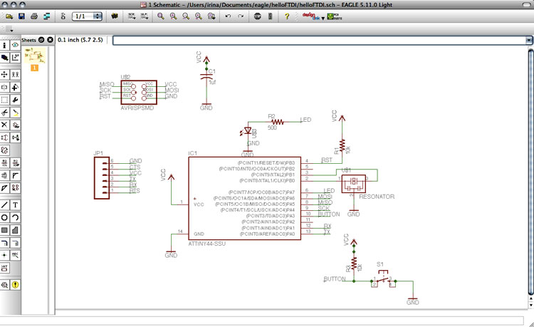
added
components:
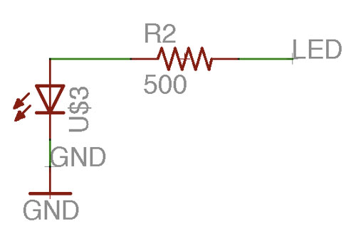 [LED
and resistor]
[LED
and resistor]
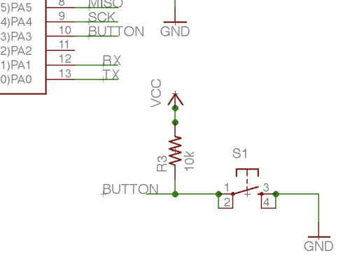 [button]
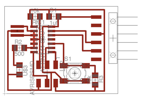
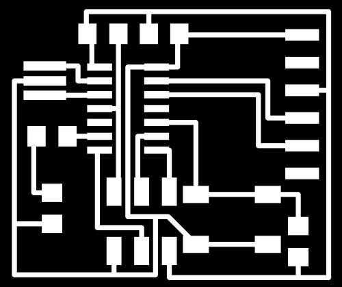
board
design png:
[After
soldering, and programming errors for several hours, we spotted the
error in the board. I accidentally connected the pins with a route,
which caused the entire board to short circuit..] Below is the first
wrong board, then the right one.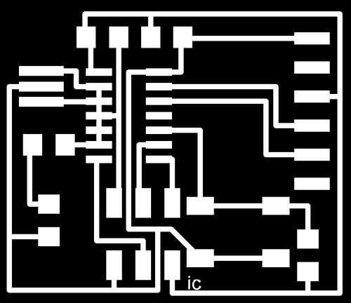
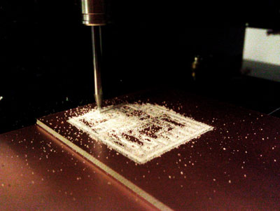
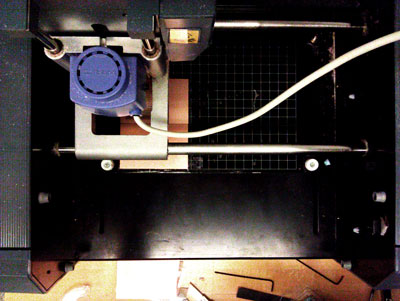
2 milling the board on the Roland Modela
Milling
was much faster this time. I changed the speed from 4 mm/s to 3.7 mm,
and the cut was much smoother and cleaner. There was an issue with
fabmodules, as the path generator was not compiling multiple cuts.
Shahar showed me that checking the XY paths under 3D settings solved
that problem.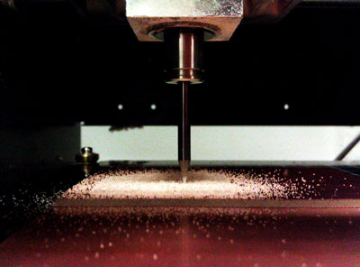
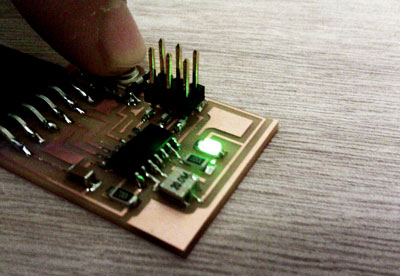
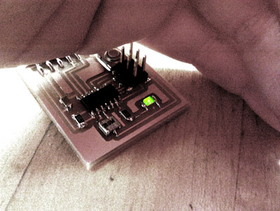
3 stuffing the board
Overall,
stuffing was smooth. Too many small parts. Be very careful while
soldering the LED, the crystal, and the ATTiny. After soldering, I
connected the board with an FTDI cable to my computer, and the LED
turned on! I don't actually think it was supposed to, given my board
was actually wrong and probably had a short-circuit...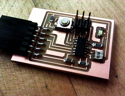
3 “programming...”
A
big thank you to Filip, Theodora, Moritz, and Brian Mayton for all
the help! Lesson learned – attend the debugging session.
All my
knowledge below.
First, check that the FabISP we made in week
[3] is actually programmed and recognized by the computer.
About
my MAC > More info > USB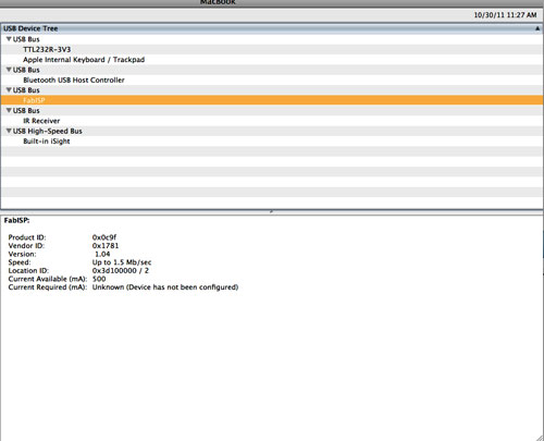
If
it is, great. Next, connect the FabISP to the computer using a
tinyUSB cable, connect the FabISP board to your new board with a
6-pin wire, and finally connect back the computer using an FTDI
cable.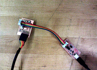
Download the hello.ftdi.44.echo.c and the hello.ftdi.44.echo.c.make files from the website. The C file is a text file that contains the code necessary to instruct how to execute the given program. Each .c files has to have a .make counterpart. You can edit Neil's .make file for new projects. Place this files into designated directory on your computer.
Also
download CrossPack,
which installs the AVR code; as well as an FTDI
serial server.
(Download MAC 64 bit)
Both of these are necessary to run through
terminal.
Open
Terminal. [Thanks Moritz for the commands!]
Open the directory in
which the files are located. [cd
Documents/, press
Enter; ls
to list all files within the directory] For example, my sequence
below. Listing all the file within the directory helps spell file
names correctly...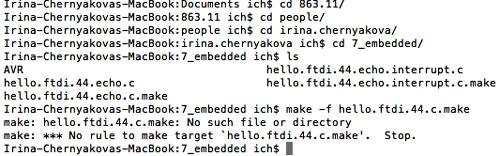
First
step is to create a .hex file. This transfers the .c instructions
into bit information [0 0 0 0 0 1 0, for example].
The command
for this is make
-f hello.ftdi.echo.c.make.
My problem at first was simply that I misspelled the file name..
Once
you have a .hex file, you need to program the FabISP fuses.
The
command for this is make
-f hello.ftdi.44.echo.c.make program-usbtiny-fuses.
If something is wrong with your board, it will give you the message
below- most likely Double check connections and try again. Try
switching the pin cable, make sure Pin 1 corresponds to Pin 1 on
both boards.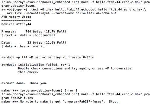
Run
make
-f hello.ftdi.44.echo.c.make program-usbtiny-fuses again.
If your board is working, connections are right, avr will accept and
execute the insructions.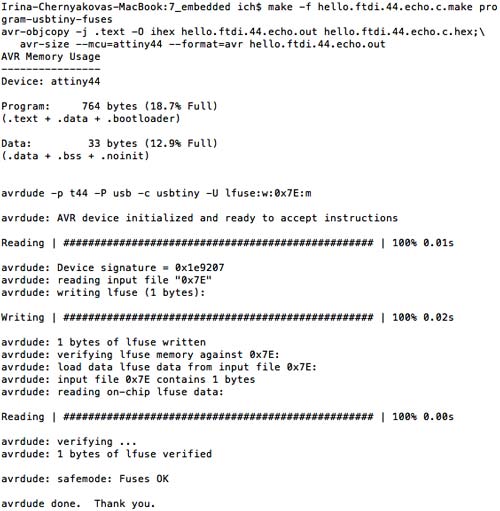
Finally,
run make
-f hello.ftdi.44.echo.c.make program-usbtiny to
program the .c instructions onto the board.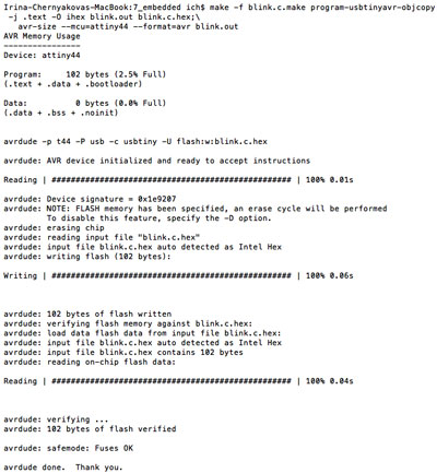
I
was having a issues with programming the fuses. After an e-mail
exchange with Brian, I thought the 20 mhz crystal may be the issue,
so I replaced the crystal, replaced the LED, re-flowed the
connections on the board and still no luck. Turns out the issue was a
route connecting the the traces of the ATTiny microprocessor...
Thanks to Theodora for letting me use her board to practice
programming!
4
“programming...
part two..”
C
+ Terminal
Moritz
suggested I download TextWrangler
to edit text for C, as Text Editor tends to damage the code. I tried
to adapt a blink code from Yeon Wha's website, as it looked somewhat
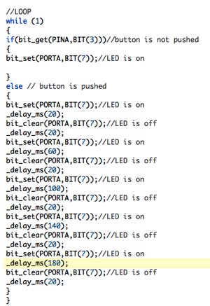
understandable. Moritz suggested I try this code that he wrote - I
first used the blink code, then modified the blink code to blink in
sync with certain beats and time variations. This is the blink.c
file
and the blink.makefile.
To run this terminal, use the same commands as above, but replace the
file name.
-
make -f blink.c.make
- make -f blink.make program-usbtiny-fuses
-
make -f blink.make program-usbtiny
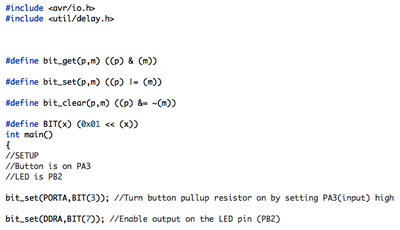
Images of the code; you can download the files by clicking on file names above.
Arduino
David
Mellis gave us a tutorial on using Arduino, which
you can download here. To use Arduino, make sure your board is
connected.
First, select the correct board: Tools
> Boards > ATTiny 44
Then,
slecect the correct programmer: Tools
> Programmer > FabISP
Finally,
Burn
Bootloader.
This
completes the set-up. Afterwards, you can run several of the example
scripts in File
> Examples > Basic > Blink or Fade, etc. Make
sure to change the LED pin number to match your board.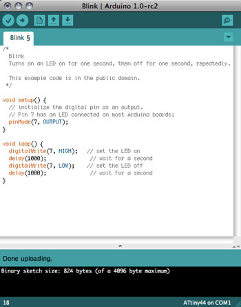 BLINK
VIDEO
BLINK
VIDEO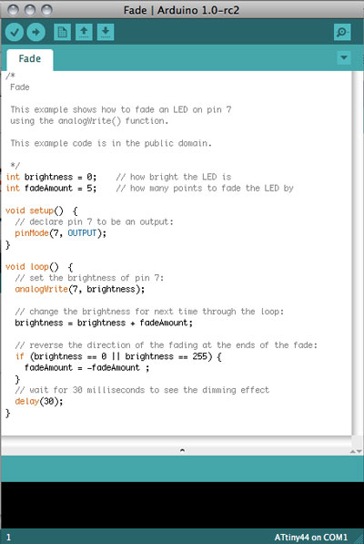 FADE
VIDEO
FADE
VIDEO