How to design and create an electronic circuit was this week's topic. I imagined that the entire process would take no more than couple of hours including the soldering part. Guess what? it didn't...
The software I used to design the board was Eagle. We were guided not to use the auto-path for the wires on the board, which means I had to find the optimal path between each point such that nothing collides and there's enough spaces. That's not easy nor fun but eventually I did it. I learned during this process that instead of using 0-resistors as bridges I can use existing resistors or capacitors. That saved me some extra soldering and made my board more efficient :)
The first board I milled didn't come out right. I thought it was the non-flat surface but apparently it was because of a damaged drilling bit, so I changed the bit and everything worked perfect. I really wondered when it will happen to me too...
The second board was much better but was really hard to solder since some copper parts were too small or with exact sizes. For example it was almost impossible to solder the resonator without cursing at least three times. So I milled a third board. It was just beautiful.
The soldering part was not too hard thanks to week 3 where I made enough mistakes and learned to avoid them this time.
Programming (extra)
I really wanted to test my board to see if it's working so I programmed it using the ISP I built in week 3.
This is what I did:
- Program the new board like we did in week 3. The only difference is that this time use the FTDI cable to connect to the computer You don't really need this step :)
- While the programmer is still attached to the new board, follow this tutorial which explains how to install ATtiny support in Arduino (don't read more than that)
- Install FTDI driver
- Open the Arduino IDE, select ATtiny44 (external 20 MHz clock) board (tools-board), your device in the serial port (tools-serial port, should be something like /dev/tty.usbserial), and the correct programmer USBtinyISP (tools-programmer)
- Burn the new bootloader (tools-Burn Bootloader)
- That's it - now upload whatever code you want and it will work (example code below)
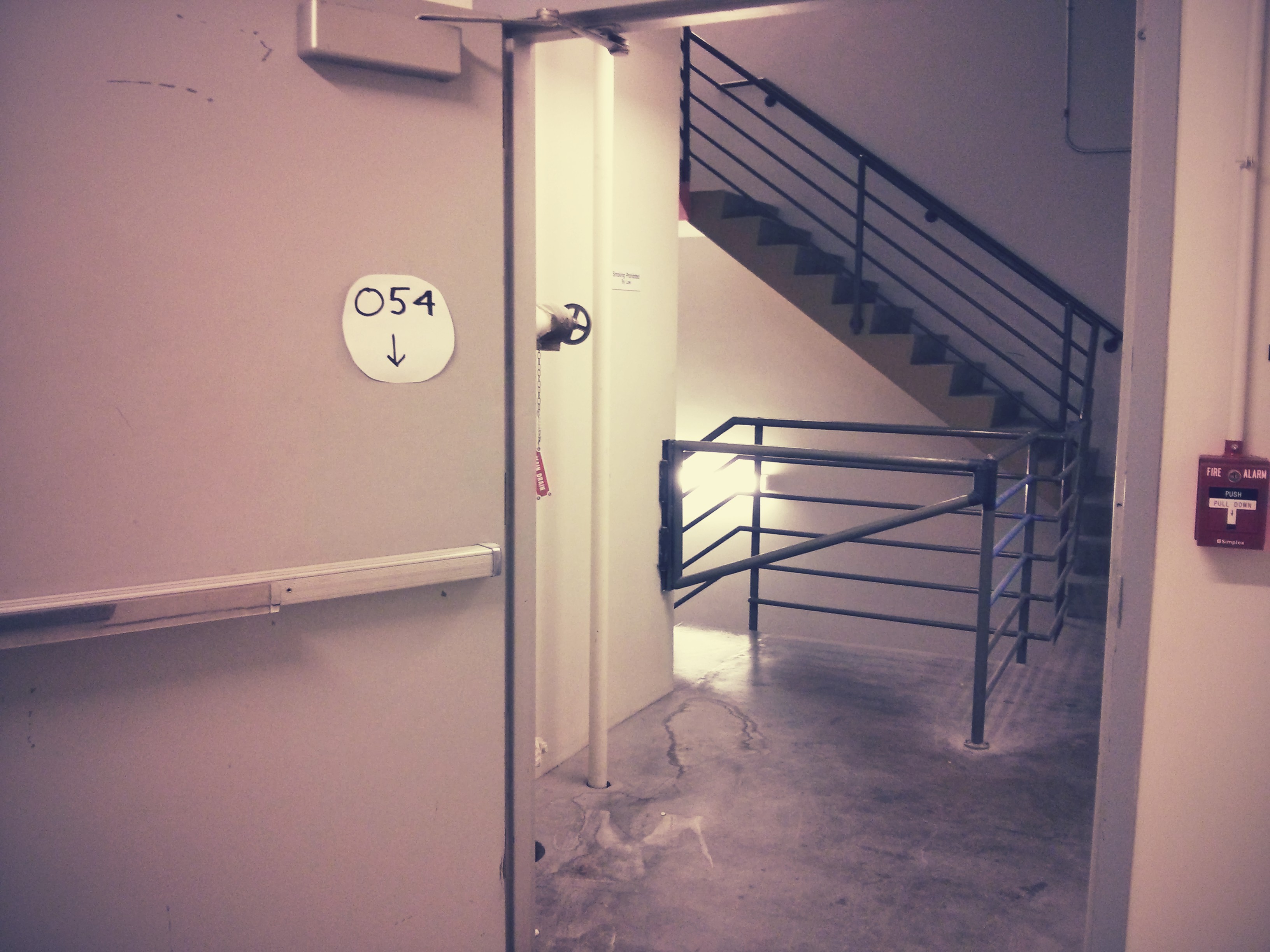
Oh!! I found a ground passage between the ground floor of E14 and E15. All you need to do is go behind the CBA shop and cross to E15, find the stairs - go down one floor and bam! you're right next to the electronics shop!
Circuit board interior + traces
ATtiny libraries for Arduino
Arduino code


