 |
||||||||||||||||||||||||||||||||||||||||||||||||||||||||||||||||||||||||||||||||||||||||||||||||||||||||||||||||||||||||
| HOW TO MAKE (ALMOST) ANYTHING MIT MEDIA LAB |
|
PROJECTS | ABOUT | CONTACT | ||||||||||||||||||||||||||||||||||||||||||||||||||||||||||||||||||||||||||||||||||||||||||||||||||||||||||||||||||||
|
|
|||||||||||||||||||||||||||||||||||||||||||||||||||||||||||||||||||||||||||||||||||||||||||||||||||||||||||||||||||||||
| NETWORKING AND COMMUNICATION - week12 | ||||||||||||||||||||||||||||||||||||||||||||||||||||||||||||||||||||||||||||||||||||||||||||||||||||||||||||||||||||||||
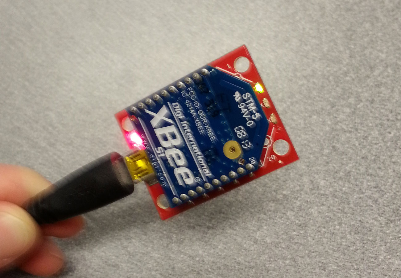
XBee's! Thinking about wireless communication for my final project, I wanted to see if I can get XBees to talk to one another from a wireless device to my computer. Here is the equipment I bought: // Xbee's (2) - without antenna // Xbee board - to connect to USB |
||||||||||||||||||||||||||||||||||||||||||||||||||||||||||||||||||||||||||||||||||||||||||||||||||||||||||||||||||||||||
 |
||||||||||||||||||||||||||||||||||||||||||||||||||||||||||||||||||||||||||||||||||||||||||||||||||||||||||||||||||||||||
| XBee with the USB explorer, plugged into computer | ||||||||||||||||||||||||||||||||||||||||||||||||||||||||||||||||||||||||||||||||||||||||||||||||||||||||||||||||||||||||
|
I used Matt Edwards's 2nd design
for the Xbee breakout board, though if you want to use this, I *highly* recommend you design the board yourself, as I needed a lot of board surgery to fix the issues
he did state in his site. I used select areas of the board and fooled the fab modules for thinking that the traces are larger than they are, using the
0.010 end mill to fix it. The datasheet
says exactly what needs to be done though, it's only a few capacitors and resistors (depending on how many LEDs you want to use), and only 5 pins on the XBee
actually need to be connected (VCC, GND, TX (UART data out), RX (UART data in), RESET). Make sure the Voltage regulator is 3.3V, which is what the XBee
needs. Other pins *can* be used for actually reading an analog signal
and sending it as a digital signal via XBee to another board, but I will leave this for later. Right now I just want XBee as a device to transmit
an input wirelessly to my computer.
Here is the final milled product. |
||||||||||||||||||||||||||||||||||||||||||||||||||||||||||||||||||||||||||||||||||||||||||||||||||||||||||||||||||||||||
| Communication | ||||||||||||||||||||||||||||||||||||||||||||||||||||||||||||||||||||||||||||||||||||||||||||||||||||||||||||||||||||||||
|
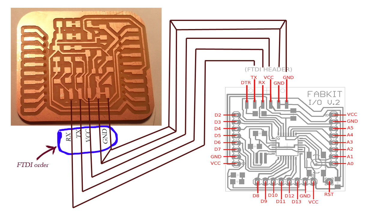
The FTDI-like connection to the AYduino does NOT need the RX/TX reversed. That is, the FTDI chip reads RX as receive signal from the perspective of
the XBee. Google FTDI for an image of the order of the wires, and this is the same order that follows on the XBee. The 6th pin is obviously not
connected and therefore unnecessary on the XBee; on the fabduino, the DTR pin is also unnecessary to connect to. See the image below for a visual
depiction of the pin mappings.
|
||||||||||||||||||||||||||||||||||||||||||||||||||||||||||||||||||||||||||||||||||||||||||||||||||||||||||||||||||||||||
 |
||||||||||||||||||||||||||||||||||||||||||||||||||||||||||||||||||||||||||||||||||||||||||||||||||||||||||||||||||||||||
| Programming | ||||||||||||||||||||||||||||||||||||||||||||||||||||||||||||||||||||||||||||||||||||||||||||||||||||||||||||||||||||||||
The program that I used to configure the XBee's was X-CTU.
Make sure to have the XBee plugged in to USB. Set the baud rate to be the same as in the serial port from which you'll be reading, and
before all else test/query. In case there is an error, follow instructions to reset OR check the soldering connection on the XBee breakout - this
was my problem.
Then under "Modem Configuration" click on Write to read the settings on the XBee. Change as needed, and in particular
change the PAN ID of each XBee to be the same, so that they can see each other. Changle also the baud rate (under Serial Interface)
to be the same as the baud rate set earlier. And then save and Read the settings to make sure they're saved. The documentation pdf on the
site above is very useful.
| |
|
|
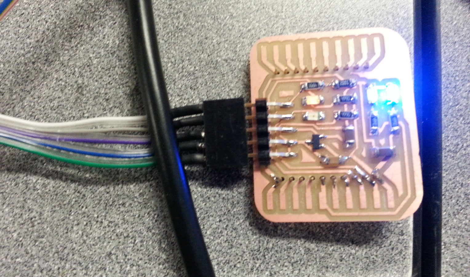 |
XBee connected to an Arduino via FTDI-like cable (Xbee on the back of the board, pins soldered on front)
|
Serial communication |
|
|
I didn't get to any fancy communication of I/O devices, but I did the Xbee's to send and receive strings via serial port when plugged into two
different computers - one via FTDI (with my breakout board), one via USB (with explorer board). YAY!
| |
|
|
Lessons Learned - electronics |
|
|
I spent quite a bit of time taking apart this little board to understand exactly what was going on. The capacitors surrounding the voltage
regulator make sense - they ensure smooth input and consistent output (not a technical explanation). The 500 Ohm resistors preceding (in direction
of current VCC->GND) LED lights make sense also, but what about the 5K and 10K Ohm resistors, acting as voltage dividers on the DIN Pin? This is a bit
of a hack to make sure that information transmitted as input (TX) to the XBee via the FTDI cable is in fact at 3.3V HIGH logic gate, not 5V. The DOUT doesn't need
this because it will be sent as 3.3V (when HIGH) anyway, since it's coming from the XBee and that is the voltage at which XBee operates.
| |
|
|
|
|
|
|
Copyright 2013 by Anya Yermakova |
|
|
|
|
|
|
|
|
|
|
|
|
|
| |||||||||||||||||||||||||||||||||||||||||||||||||||||||||||||||||||||||||||||||||||