 |
||||||||||||
| HOW TO MAKE (ALMOST) ANYTHING MIT MEDIA LAB |
|
PROJECTS | ABOUT | CONTACT | ||||||||
|
|
|||||||||||
| FINAL PROJECT - week15 | ||||||||||||
|
|
|||||||||||
| An interactive system in a tetrahedron | ||||||||||||
| Check out videos first! The Piezos are embedded into the tetrahedron from week 5, and the dancer is free to move around/in it, wirelessly feeding information to the Piezos (and other output devices I didn't get to..!) | ||||||||||||
Accelerometer as point of inscription on shoulder, with wireless feedback to piezo disks from Anya Yermakova on Vimeo.
Dancing with the shoulder. Accelerometer reading movement in 3 axes, sending the information to 2 piezo disks, wirelessly
| Accelerometer | ||||||||
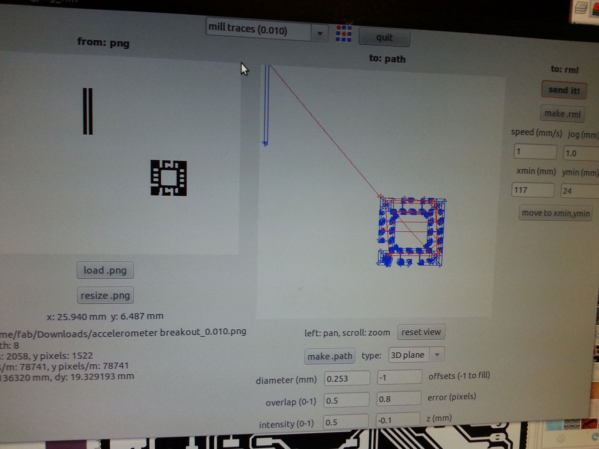
| So I decided to start with making the accelerometer. The question was - digital or analog? The digital one - LSM303DLHCTR - well, is digital, and I haven't played at all with I2C. A little intimidated of what will happen there. But is in the inventory and there exists already an Eagle file for it. The analog one (3-axis) - ADXL337 - is not in the inventory, and only has the 3-axis input. I went with the latter, and designed my own library file for it. Designing the file for Eagle.. dimensions taken from the datasheet above. And this was a great tutorial to follow, if it's your first time. Note that the little pads for the accelerometer chip came off during milling, but as they were unnecessary for any kind of function, and as the middle pad held down the part anyway, I decided to not worry about it. Note that this chip takes no more than 3.3V, so make sure the voltage regulator is 3.3V, especially if the FTDI cable you will use to connect it is 5V. Download the eagle and png files here. I used the 0.010 end mill for the really thin parts of the breakout board - in a separate png file. Note that it's ok to just allow the fab modules to avoid those really thin areas using the 1/64 end mill, and then go over the places it did not touch with a separate png file specifically for the 0.010 end mill. See an image of the settings. | ||||||||
 |
||||||||
| milling separately the thin parts with 0.010 end mill | ||||||||
| Soldering This was the first time I used solder paste, and also the first time I used the reflux method. I must say, it was exciting, but also I ended up just going through the connections with the soldering iron afterward anyway, just a thin, clean tip. It seems that first soldering the pad under the small chip and then small dabs of solder, teasing them with the iron, which I think is called drag soldering (provided the tip is small and clean), is just as good as reflow. | ||||||||
 |
||||||||
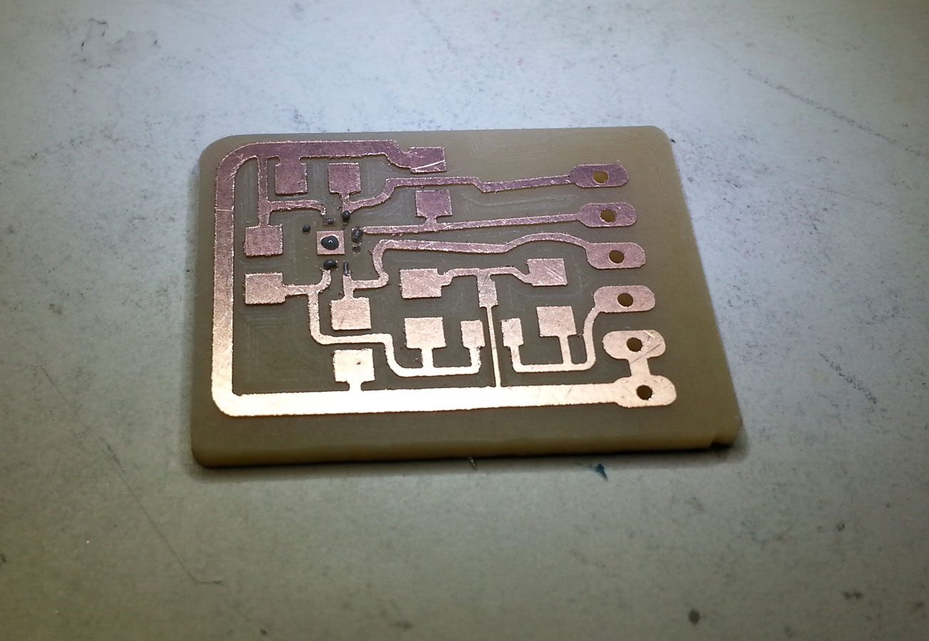
| milled board with dabs of sodler paste. I used the advice of the datasheet to stick some capacitors on there, 1 for each input reading, and 1 for regulating the charge on the whole board. All 0.1uF. | ||||||||
 |
||||||||
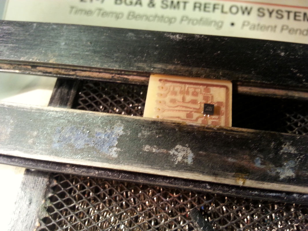
| IR reflow | ||||||||
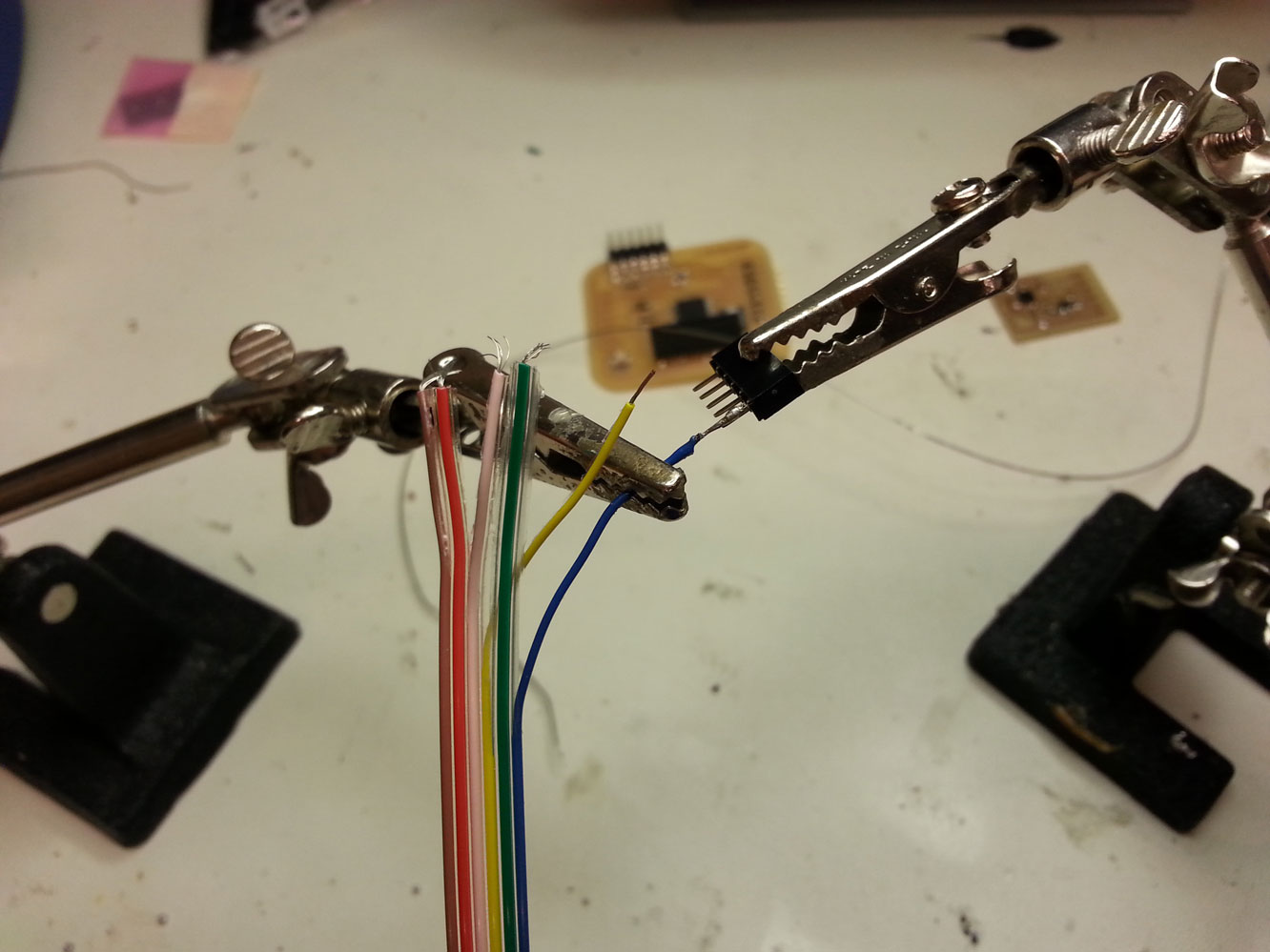
| Connecting breakout board to AYduino Following the data sheet, all that needed to be connected were GND, VCC, and 3 analog input pins - one for each of the x,y,z directions that the chip is reading. This did, unfortunately, take up 3 of the 6 analog pins on AYduino right away, but still left 3 pins open for using the breath belt, if I get to that! | ||||||||
 |
||||||||
| a helping hand for soldering pins to connecting wires | ||||||||
| Programming This was a helpful tutorial for basic code in Arduino. And it seems to be working! Though, the range of inputs is not so responsive, as in static state the acceleration (due to gravity?) is not negligent. The real way to calculate movement, then, is to take difference in values from one reading to another, in x,y,z directions, separately. Short video of the serial port (as seen in Arduino IDE), programmed with Arduino code here: | ||||||||
Serial read from 3-axis analog accelerometer from Anya Yermakova on Vimeo.
| Accelerometer via XBee's to Piezos | ||||||||
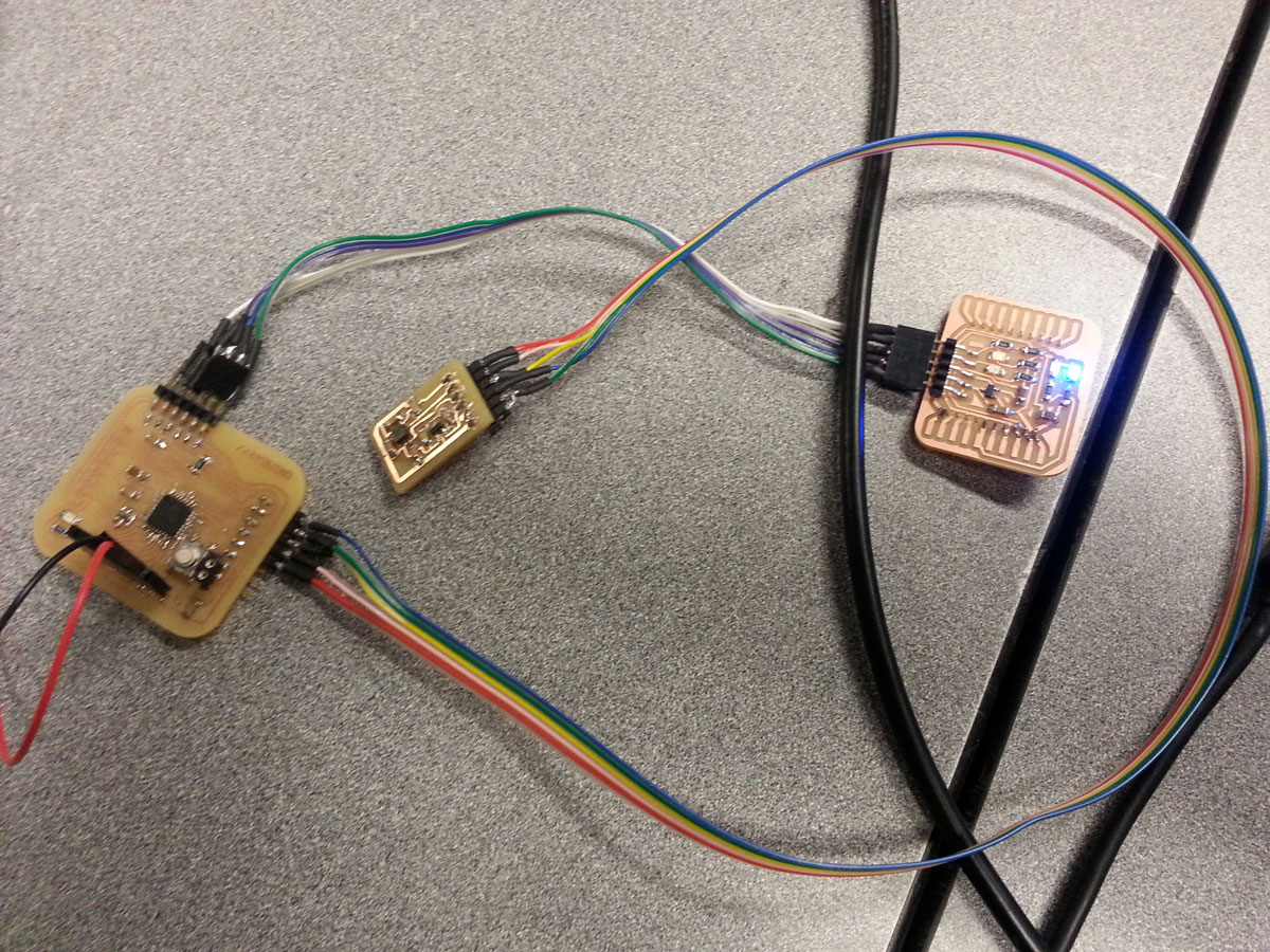
| I used the programmed XBee's from week 12 to read data from the accelerometer and wirelessly transmit it to one serial port (USB connection with another XBee) to my computer. Here's the wireless set up (the red and black wires are to a power source of <=5V): | ||||||||
 |
||||||||
| the wireless component | ||||||||
| Programming From another serial port, connected via USB to AYduino 1.0, the signal from the accelerometer is interpreted to trigger piezo disks. The programming that needed to be done included the AYduino 2.0 to read the data from the accelerometer (programmed in Arduino), sent via XBee's (programmed with X-CTU) to my computer's serial port, where an interfaced (written in Processing) sends "interpreted" signals to AYduino1.0, which, (programmed in Arduino), tells the Piezo disks to vibrate or not to vibrate. The videos below outline this process, and below that there is all the code used. | ||||||||
Final Project Explanation of electronics pieces from Anya Yermakova on Vimeo.
An explanation of all the interconnected pieces of the electronics set up. AYduino2+battery+accelerometer+XBee (wireless) --> XBee+computer's serial port1 --> Computer's serial port2 (FTDI) --> AYduino1+piezo disks
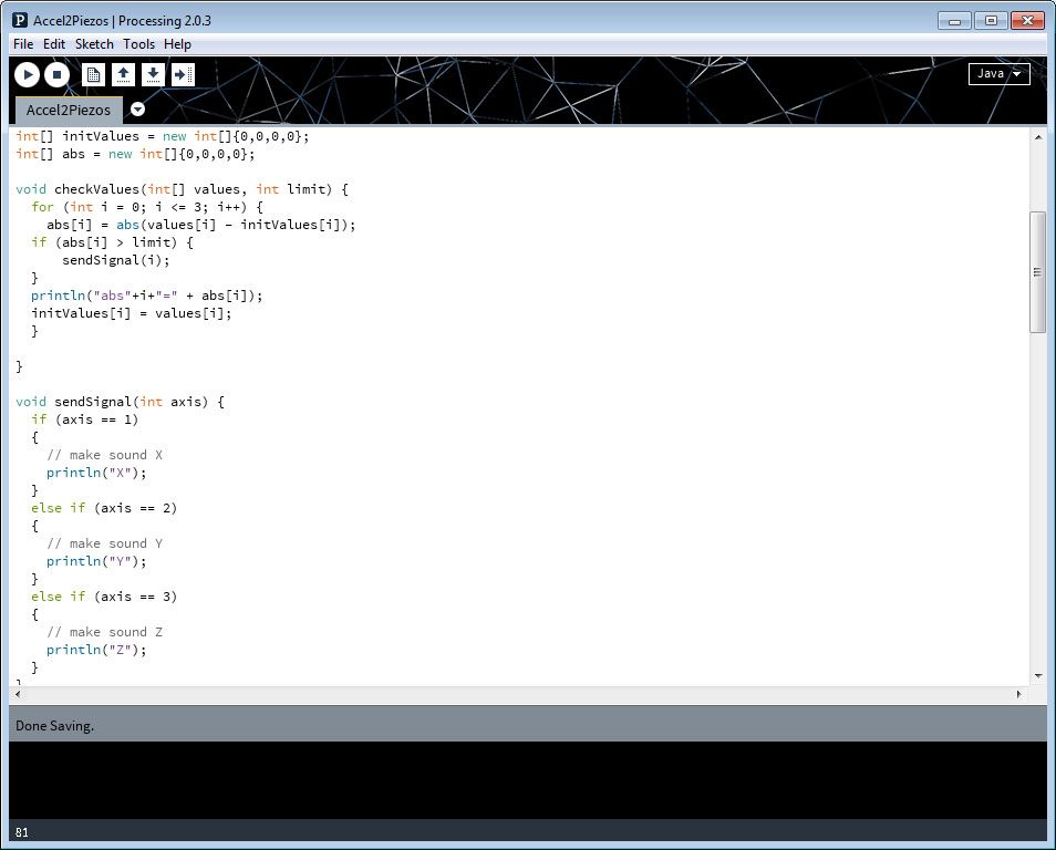
| The Code The interface to read accelerometer data and output it to trigger piezos was written in a combination of Processing and Arduino - Processing to read signal and interpret it, Arduino to write it to AYduino with piezos according to string received from the first port. I wrote two functions to assist with this in Processing, since I noted that the acceleration values in themselves are always high (due to gravity). The actually interesting variable to read is the *difference* between one instance to the next of values on each axis. See the image below for what those functions were. | ||||||||||||
 |
||||||||||||
| Two functions in Processing, for interpreting accelerometer information and writing them out to Serial Port | ||||||||||||
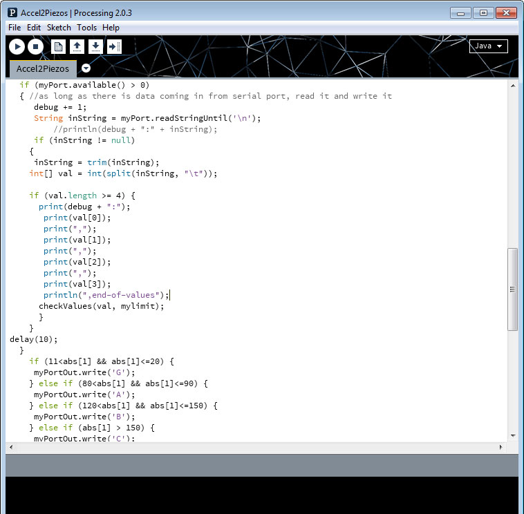
| In port setup(), this was how I defined the two ports: myPort = new Serial(this, Serial.list()[1], 9600); //open the port you're using at the rate you want from which you'll read myPortOut = new Serial(this, Serial.list()[0], 9600); //open the port to which you'll write The next task was to figure out how to transfer those differences into something that could be sent via the serial port. I decided to take small windows (with gaps in between) or absolute difference values defined above, for which a single character would be sent from portIn to portOut. There is much much more room to play with these parameters, but these worked for the first try. | ||||||||||||
 |
||||||||||||
| writing characters to second Serial Port, depending on difference in accelerometer values. Depicted function is inside void draw(). Visualized is for x-values of acceleration only. Click on image for full code. | ||||||||||||
| Finally, download here is the simple code in Arduino to get these Piezos to make sounds in response to receiving certain characters from the Port. This was a bit of a hack, taken from the code in Output Devices week when I made piezos make pitches, but again it worked for first time. | ||||||||||||
| Debugging: // sometimes if there is no connection, change [0] and [1] in the serial code (or change around the USB connections). I don't know how the computer determines which COM is which, it seems to number them differently every time. // This seems silly, but in order for this to work, make sure both of the USB's are plugged in (the XBee to communicate with AYduino2 and the FTDI connected to AYduino1) // The piezos here were really not the ideal output, first because they are annoying if you try to do pitches with them, and second because they are very quiet. I used them for debugging because they don't need a separate breakout board, but for second iteration of this, it would be much wiser to use small MOSFET speakers. // As mentioned above, the windows that I defined in the Processing code to send strings via serial port were a bit arbitrary. I left gaps between defined value differences to make sure there is some silence and the piezos are not just on all the time. However, it would be more interesting to set up an experimental construct in which I devise these values in a more systematic way, reflecting actual movement observations. // I didn't get to the 3rd piezo disk for z-axis, in part because the wire soldering came off and I ran out of time to fix it. Would love to clean up this code and get all 3 piezos involved; then move on to speakers. | ||||||||||||
| What's left: // Tetrahedra! Taking my design from week 5, I need to make a small extra bit to make sure the top tetrahedron fits on top of the bottom two. As is, it is too crunched and is short of fitting on top of the bottom three. // Finish programming 3rd Piezo, clean up code, and then change piezos to speakers! | ||||||||||||
| A massive thanks!!! | ||||||||||||
| To Neil and everyone in the class for the incredible learning experience and the inspiration, and in the last crunch time for the final project specifically, a special thanks to Matt Carney, Will Langford and Nadya Peek for their help!!! | ||||||||||||
| Copyright 2013 by Anya Yermakova | ||||||||||||