Output Devices
This week I made a circuit board that talks to a speaker. I designed my circuit board last week so that it could be used for audio IO simultaneously.
Debugging! My first mistake was to misunderstand the very simple low pass filter I used to remove DC from the output. I had two resistors soldered in parallel where I wanted only one resistor soldered in series.
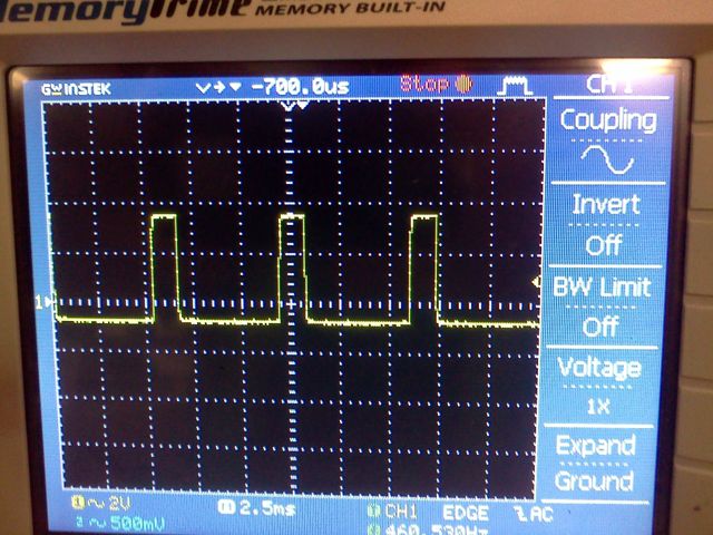
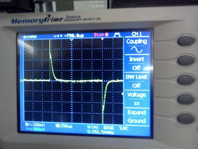
Having a speaker output on the board is great because I can debug with my ears -- this is much faster than debugging with a scope. However, in most cases, ears are phase in-discriminant, so the the image above and the image below both sound the same.
 Process:
- Write
void init_pwm()such thatvoid out_duty(char)accepts a char, and uses that char to set the threshold for non-inverting fast PWM on an output compare pin connected the the audio out - Make sure that I can generate a saw wave, using code that looks like this
Note that I can't use a scope to identify waveforms perfectly, because the phase shift introduced by my high-pass filter prevents waves from looking like their names (ie saw, triangle, etc)// assume #include "output.h" // clock divider to 1x TCCR0B = (0<<CS02) | (0<<CS01) | (1<<CS00); static unsigned char level = 0; init_pwm(); out_on(); while (1) { out_duty(level++); } - Use the other clock to generate an interrupt at a much slower clock cycle (maybe 20khz). Write a "sample" to the output pin by specifying a duty cycle
- Add an audio output (queue data structure?). During the main execution loop, try to keep the queue full. During the interrupt remove a sample from the queue.
// Initialize the clock
TCNT1 = 0;

// start Timer Counter 1
TCCR1B |= (1 << CS10);

// generate an interrupt when clock matches 511
OCR1A = 511;

// CTC (Clear Timer on Compare)
TCCR1B |= (1 << WGM12)

// Timer Counter 1 Output Compare A Match Interrupt Enable
TIMSK1 |= (1 << OCIE1A); // ISR(TIM1_COMPA_vect)
Debugging: The TIM1_COMPA_vect interrupt was triggering, but not only when then counter maxed out at 2^16 - 1. For some reason the OCR1A value was not triggering a counter reset. I couldn't figure out why not, so In the end I finally opted for just writing some arbitrary melody in to the main execution loop using
_delay_ms() instead of the sample rate interrupt.
Finally while I was writing documentation, I figured out why my Clock was not working as expected. When setting the Wave Generation Mode Register
TCCR1B |= (1 >> WGM12) I used the right shift operator instead of the left shift operator. DO'H!!! I was so focused on checking that the registers where correct, that I didn't notice the wrong operators.
My code got a little messy during the extensive debugging process, but it also get very well commented:
I also noticed sparse undesirable energy at 98000hz and the first harmonic 196000hz. I think that has to do with the pwm style of synthesis, and it should be pushed out of the audible range by setting the clock divider to 1 instead of 8.