Week 10: Input devices.
1. Make a simple board of Neil's design to figure out the process:
- In order to work out the details of programming and using the tiny45 micro, I cut and stuffed the thermistor board from Neil's examples.
- Programming and communicating:
- I determine that my tinyISP progammer is working by reprograming my former tiny44 board to blink. The new tiny44 temp board does not work initially, giving me errors when programming with the arduino environment. board with Arduino code. Rob Hemsley diagnoses sodlering issues, and when he reflows some of the pins on the tiny45, the programming is successful.
- In the meantime I made a second board. As a diagnostic step this is not a bad thing to do for such small boards (for a novice). I did a better job of soldering this and it worked first time.
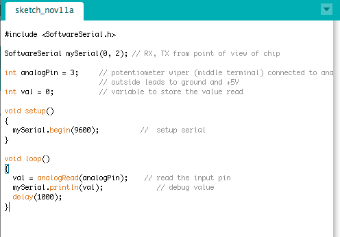
- The tiny45 board does not have native serial capabilities. In the Arduino environment, one can use a software serial method. Below is a simple code that reads analog input on pin 3 once per second and send to a serial port.
- When the code is run I can see the reuslt using the serial viewing function in Arduino, which is accessed uring the magnifying lens icon on the upper right of the project window. The correct serial port choice is /dev/tty.usbserial-FTGOS6P.
- The numbers received seemed to make sense - about 125, or half of the 156 maximum, (I did not record this and don't remember the dtails - may be wrong about the numbers) for the pin halfway between vcc and gnd. The value changes when I touch the thermistor.
- Here is the Arduino sketch.
- Now program the device using Neil's code (hello.temp.45.c) from the examples. I pasted the code into an Arduino sketch and uploaded. No errors, and using the terminal vie I could see characters coming in. The characters did not correspond to numbers - in order to interpret the data stream I need Neils python program.
- I got the python code to work: hello.temp.45.py. Here are some of the things needed:
- Make sure that the python extensions are there. Tkinter is a Python GUI library that is called to make the display. numpy is a numerical library that can be downloaed and installed from the Python site.
- Use the serial port name when calling the program: " python hello.temp.45.py /dev/tty.usbserial-FTGOS6P" works.
- When the program runs successfully I get the colored bar that changes with temperature and give me numbers in the range 20-25.
- The display freezes after a few seconds. This may be due to the fact that the internal clock gets out of synch with the terminal. I think that this is solved in Neil's makefile where the bit delay is adjusted. Can I do this from Arduino? Do I need to use the command line toolchain and Heils makefile?
- Now I can, in principle, modify and use Neil's Python/C examples......
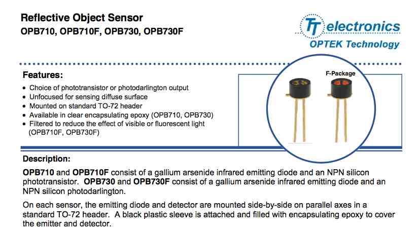
2. Make my own board using the Optek sensor. link to Optek.
- I made a board to measure a signal from a optical proximity sensor. This sensor is available for ~few$ form DigiKey.
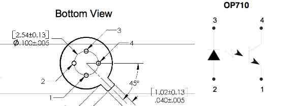
- Optek data sheet
Traces below:
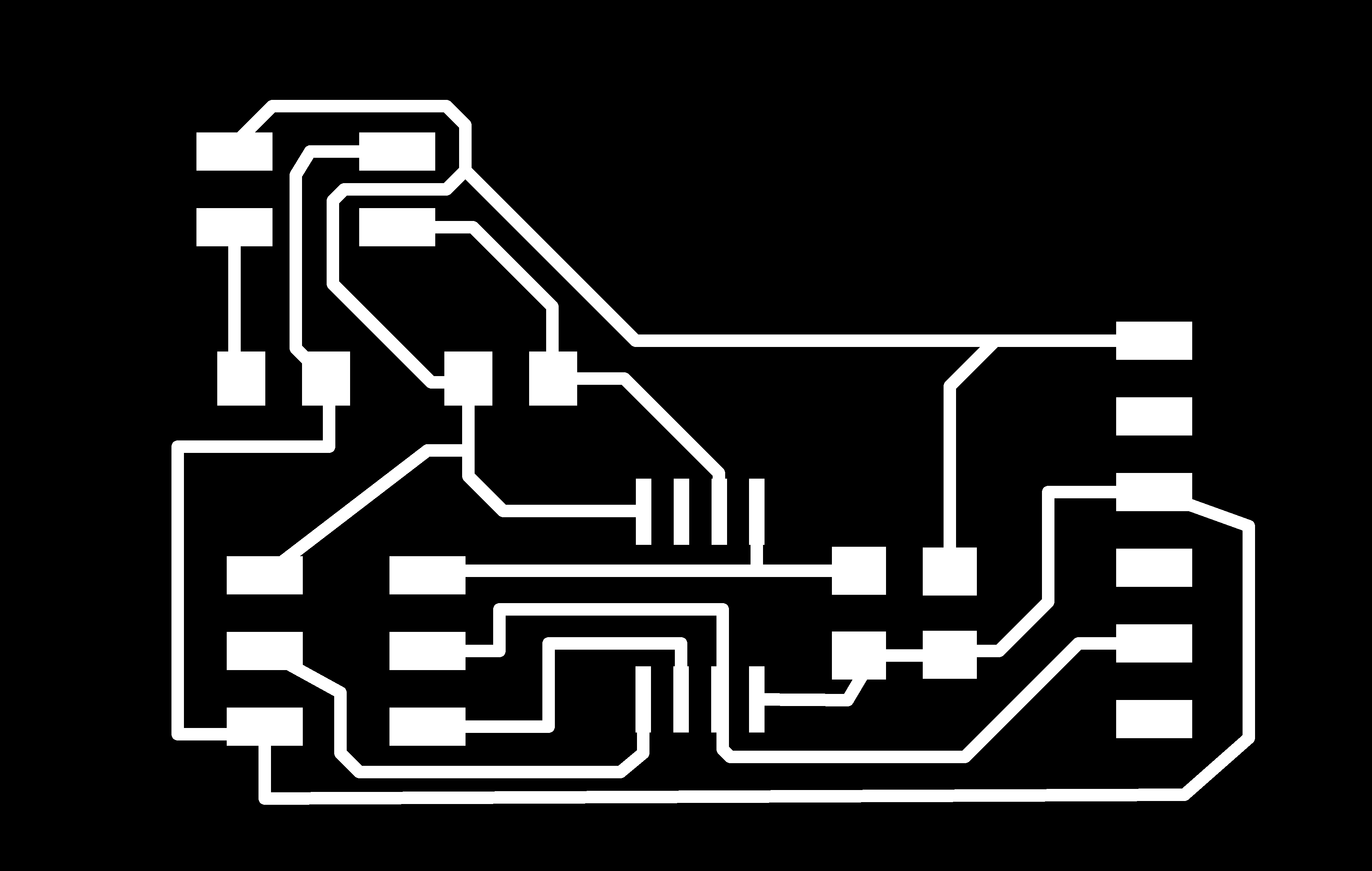
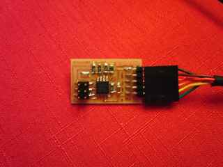
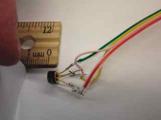
Below is the board with sensor attached. The board provides LED current and phototransistor bias to the sensor as planned.
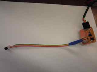
I was able to measure a signal by oscilloscope on the input pin to the ADC. The setup is shown above, and the results below. More complete results coming soon!
Measurement of output voltage vs distance of white card from sensor.
| Distance (mm) |
output at pin (V) |
| >>10 |
0.03 |
| 10 |
0.08 |
| 8 |
0.15 |
| 6 |
0.22 |
| 4 |
0.38 |
| 2 |
1.22 |
| 0 |
0.26 |
I was able to program this board with my repaired Tiny44 ISB programmer using the simple Arduino code. The program sends values via SoftwareSerial from the tiny45. The values range from 0 to 1024, reflecting the 10-bit ADC. At a lower level in the code the two bytes are being combined. In Neil's code both bytes are sent out to the Python program, which combines them.
3. Explore the use of the step response devices.
Next, I want to use the step function repsonse sensors. This could be directly applied to intro physics E&M labs to have students do something useful!
Joshua Smith's thesis is one resource: http://cba.mit.edu/docs/theses/95.08.smith.pdf. Neil showed a video from JS's thesis of 3D field sensing of hand position using an arry of electrodes.
4. Notes from class 11/13/13
- hello_radio-16 Shelby Doyle
- c-w wang: LED ambient light detector. In this mode reverse bias current is related to light intensity. LED detects light by charging up its internal capacitor. Measure time to discharge. Read as A/D. Better to use comparator. Set one side as bandgap reference.
- Chris Martin. Music generated by light modulated by moving screen. pyserial use.
- Jeff Geisinger. Using pyserial: Neil uses rx.py to diagnose serial port issues. Software switchable pins by using many resistors in series with pullup. Many ARV chips available with more pins. eg, atmaga88. Bicycle shed. Humidity sensor. Accumulate charge/discharge cycles. Get precise measurement of capacitance by taking data over long time. Need bigger words, can define. Can measure capacitance to high enough precision to see humidity effects.
- Taylor Levy: Wants to try to use LSM303 accel chip.Talk about solder paste and reflowing. DIY solution: Frying Pan!!
- Basheer Tome: Capacitance sensor. Roughly, the size of the plate gives the range.
- David Yamnitsky. He made a homebrew installer for stm32 processor.
- Pauline Varley: Pencil lead using step response sensor. Laser printer toner is also somewhat conductive.
- Akash: cap sensor for slider. Eight pads in chevron shapes.