Week 5: Computer-controlled machining.
Assignment: Make something BIG.
Tromba Marina: Introduction and background of this idea:
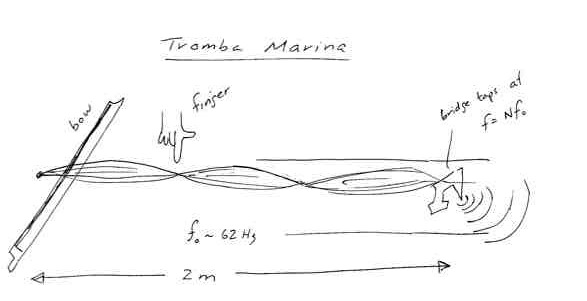
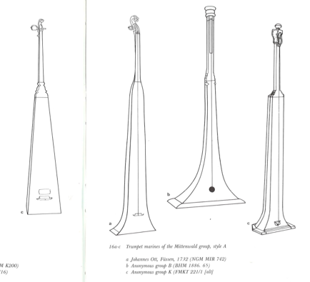
The Tromba Marina, or Marine Trumpet, is a BIG string instrument that flourished (?) in the 17th -18th centuries in Central Europe. It has a single string of about 2 meters length, typically tuned two octaves below middle C. The string is bowed near the head end with a finger exerting light pressure near a node, so that the string vibrates at the frequency of one of its harmonics. The bridge has one foot planted on the soundboard and the other placed so that the oscillations induced in the bridge cause it to tap against the resonant body. The taps at the frequency of the harmonic give the sound a rich timbre with lots of high frequency content, reminiscent of a trumpet. And since the frequencies are multiples of the string frequencies, the pitches playable are analogous to those of a valveless trumpet. More details in the book by Adkins.
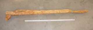
The idea for this week is recycled. I made a prototype a few years ago to use for a class in the physics of music. It is a monochord demonstration box with a stick attached as a neck. It worked, although the bridge was never quite right, and never in good adjustment. Furthermore, it's ugly, hard to store because of its size, and not easy to hold in playing position.
Here are some improvements I would like to make;
- Create a structure to support the string tension and hold the bridge. Make it foldable so that it is portable!
- This will then be a platform for development of bridges and resonators.
- Optionally, do away with resonator - put an accelerometer on the bridge and make it a portable electric tromba marina.
- Make a more graceful structure that lends itself to playing.
Some design notes:
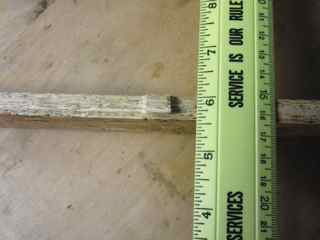
- String length 2 meters.
- Gut string diameter 0.092-0.095"
- String tension 400 N.
- Note that some sources put the fundamental pitch down one more octave. That would make tension only 100N. That's not consistent with what I think I know about playing pitch. Need to check this with MFA.
Design of parts
- I will use OSB. It may be no the appropriate material for handling the string tension, but it will make a prototype to test form and folding and dimensions. And it's available and cheap and good for learning.
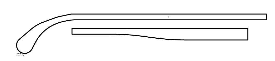
- Sketch from Solidworks file
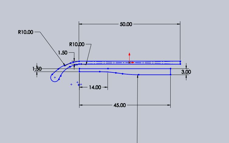 This sketch was saved as a DXF to import into Partworks.
- Make two of each. The curved head parts will hold the tensioning screw. The straight tail parts will fit around the head, overlapping about 15". The head and tail will be attached by bolts, allowing them to pivot for folding. In some future design they might pivot and interlock without bolts.
Making parts on the Shopbot
Akash and I ran our parts together, for safety and better learning - thanks, Akash. Steps for shopbot on Windows:
- Open Partworks, set up new file. Set correct dimension, zero at the top of the material, set material thickness.
- Note how coordinate systems (computer and table) map onto one another.
- Import file, or create drawing in Partworks.
- Tool paths.
- Create profile path (since we are cutting through the material.)
- Set cut depth. This is the total depth, a few thousandths larger than the thickness.
- Specify tool parameters, speed, feed, plunge rate, depth of cut (<~ tool diameter.)
- Specify cut side (in/out/left/right) Check that this is what you want using preview.
- Specify conventional or climb milling.
- Add tabs.
- Name toolpath, calculate and save path.
- Check toolpaths that you want for the run, and save toolpaths to part file.
- Fixture the job. Use sheetrock screws to fasten material to sacrificial layer. Can make a toolpath for drilling holes to locate screws.
- Run the machine
- Turn on power.
- Open shopbot software sb3. May need to reset with the blue button.
- Use the keypad to jog the head and move it to get access to change the collet.
- Change the tool and check that it is firmly in the collet and the collet tightened.
- Jog the head with the bit to line up with origin and zero x and y.
- Use the zero plate with alligator clip to zero the z-axis (menu item under 'cuts').
- Load the part file.
- interlock key turn one click to the right.
- Turn the dust collector on.
- Run the job.
- Start the spindle. Check to see that the displayed speed matches the speed set in sofware.
What we learned:
- Importing drawings into Partworks: Imported DXF files come into Partworks in the form of many individual line segments. The sense of "inner" and "outer" depends on the curvature of the segements, and often seems unpredictable. This chops up the toolpaths and makes it easy to make mistakes. We approched this problem in three ways:
- Redrawing the source files with an offset so that we could use tool paths on the line instead of to one side.
- Selecting "inside" paths for some segments and "outside" paths for others. Make sure to preview.
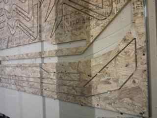
- Redrawing the design in Partworks as a polyline. The tool path is then a single pass as an outside cut. This is what I did, but still made the mistake of making one of my sets of cuts "inside" with the result that one set of parts was 1/4" too small (one tool diameter) all the way around. See above right.
- Feed and speed and choice of tool. We broke an endmill close to the start of our cutting.
- We were using a long (2-inch flutes) two-flute bit with 1/4" diameter at a spindle speed of 10,000 and a feed rate of 100 ipm with a cut depth of 1/4" (equal to the tool diameter). This is a chip load of 0.005" per cut. Perhaps too large for the long bit - I need to find out more about the specifics of the tool. Charles points out that long bits like this one should be reserved for situations that require their depth of cut. (eg mold making)
- We switched to a shorter bit and increased the rpm to 18k. The 1/4" bit listed in the fab inventory is the Onsrud 52-280, a two-flute carbide bit. On the Onsrud website the series number for that bit is given as 52-200. The Onsrud website also has data on feeds/speeds :https://www.onsrud.com/plusdocs/Doc/index.html?model.code=FeedSpeeds. For that series number the specified chip load is 0.007-0.009" At our speeds/feed the chip load was 0.003 per flute, well below the suggested range.
- I see some discussion on the lists indicating that low chip loads can lead to greater tool heating since the tool is cooled mostly by its contact with new material. Larger feed rates spread the heat load out into a larger volume of material. Looks like choice of feed is a balance between risk of breakage and increased heating.
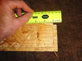
- Tabs. For OSB it is best to keep tabs numerous and large - about half the thickness of the board. Easy to use saber saw and hand tools to remove tabs after machining.
- Fixturing and loose parts. It would be a good idea to create drill toolpath to place more screws around small parts, especially Akash's floppy bird things.
- Several of the parts that we cut were too close. We tried to conserve material, but lost parts due to the fact that not enough material was left to support tabs.
Building and Assembling the Tromba
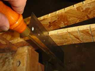
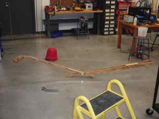
- Trimming and reshaping. I trimmed tabs and made the outlines of the parts uniform. Due to my mistaken toolpath, one set was too large by 1/4" offset of the perimeter. I removed this excess with a bandsaw and planed and sanded the tabs. On the right above is a tab that was made almost as thick as the material itself. This worked better thatn the thinner ones - used a saber saw to remove the part from the surrounding material and planed/sanded the remaining tabs.
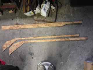
- Bending and gluing.
- For the head (left), I glued in some solid wood (old oak and maple flooring) as a core to hold the nut (top of vibrating length of string) and the tensioning screw. I made a gentle bend in the OSD by fitting in an oversize wedge.
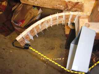
- For the tail (center and right above), I wanted a more extreme bend. I cut slits in the end foot almost all the way through, and filled the grooves with glue and paper. The paper was intended to hold the glue. Should have used paper towel? This is related to my cardboard bending technique in week 2.
The results:
Insert picture of head details. Show that the tensioning screw is located out of sight. The curve and the straight segments look good. The curved section fits over the shoulder and allows good access to the part of the string needed for playing.
Picture of tail. The bend is a bit clumsy, and the result flimsy. With some more strenght and redesign it could look good and provide a wide base for playing. Maybe a longer, wider curve. It needs some rubber feet.
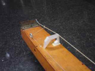
Bridge picture. The current bridge functions, and taps against a glass slide on the body.
Picture of someone playing it.
Link to a wav file of the sound.
Picture of it attached to bicycle for transport.
.
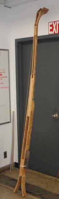
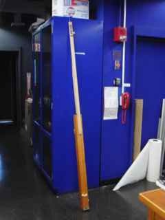
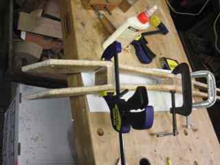
The assembled parts are above. On the left, the folded-up structure with head tucked into the tail. In the center, the instrument with string attached, in the process of tensioning. On the right the string under tension and the parts bolted together. It is already clear that the neck is bowing.
Notes from class 10/9/13
- Use dogbones for corners
- Leighmon will run another Solidworks seesion soon. Sat 10/19 1:00 PM E14-140. RSVP. Global variables in Solidworks.
- Alternative to mess with importing into Pathwork: Save as svg, use fab modules to make *.sbp file. Export selection as a bitmap, then png to shopbot, enter offsets. Time to load and play with Fab Modules.
- Making parametric tabs in Inkscape: Create tab, clone repeatedly. Eport as png.
- Kokopelli. Initially parts of Fab modules, extensions of Python. Matt merged the pieces into one. Will has used Kokopelli, and offers to help.
- Dyvikdesign.com laminated 2D chairs.
- Kristen made flex sheets. Kirsten also made a flex chair.
- Matt Carney spoke about creating 3D surfaces from pointclouds. Gorilla glue to glue foam.
- Use cad in fab modules to make surface representation of arbitrary math function. Shapes in fabserver.
- Casting material: hydrostone.
- Charles Holbrow created a function in solidworks. Made 3D graph.