Week 8: Embedded Programming
Assignment: Read the data sheet! Program a microcontroller to do something in as many languages in as many programming environments as possible.
I followed David Meliss's tutorial on using the Arduino development environent and language to program the ATtiny44 chip using the FabISP board. The tutorial is detailed, and I was almost successful at programming without help. Charles Fracchia helped me get there. Here are the extra things that I needed to know to get it to work, and a few other useful things.
- Below is the arrangement of programmer and board. The FabISP programmer is plugged into the USB port of the computer and connected to the ISP 2x3 header on the ATtiny44 board. Since the header is oriented the same way in each board, I just needed to orient the connectors so that the same color was on the same side for both headers (blue on the right in this case). This does take some attention the first time. It was necessary to refer to the schematic and pictures of the board layout as I connected power and programming cables.
-
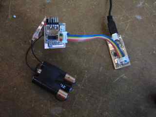
- Power for ATTiny44 board. The ATtiny board needs to be powered externally. The Vcc and ground connections in the ISP header do not provide power. The most convenient may be to use an FTDI cable plugged into the USB port. Pictured above is the power supply that I used when I had no cable available: 3x1.5V batteries=4.5V clipped to the GND and VCC pins of the six-pin header.
- The FTDI cable is going to be a useful object. It contains a chip that translates between USB and the serial signals compatible with the microcontroller. It is necessary to download drivers. For a start, it is useful to provide power. It will be used for a serial link to computer.
- Sequence of steps once Arduiono is running with the files loaded that define the board and programmer options (instructions for this in tutorial).
- Find ISP programmer in the list of USB devices. (About this Mac > more info > system report) At times the FabISP disappeared from the list, and it was necessary (suffiicient, anyway) to restart.
- Choose correct board. In our case, choose 20MHz external. The Arduino software sends the right message to the micro to run the clock with the external 20 MHz oscillator.
- Burn bootloader. I do not fully understand why a bootloader is needed here, what it does, and why it is needed when we have a programmer attached. I will figure it out.
- I loaded the blink sketch from the examples, and modified it: Blink_rob.ino. Also modified the button program to make my button on pin 10 turn on the LED.
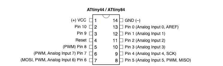
- The pin nomenclature could be a bit confusing. For instance, my LED is connected to pin 5 of the chip, which in the Arduino environment is called pin 8, and according to the datasheet is PB2, among other things. Below is a figure from the David Mellis tutorial.
- The blinker worked. I can control the rate and duty cycle.
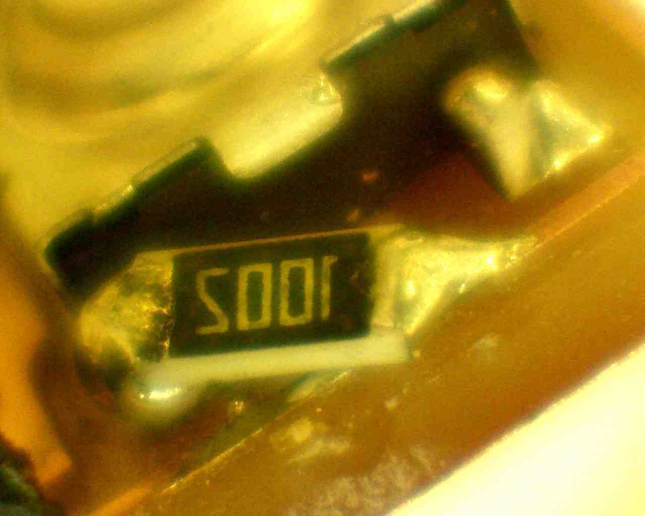
- The button required the addition of a resistor between VCC and the switch so that pushing the button does not make a short between VCC and GND. This was a mistake in my board design due to my misunderstanding of the discussions about internal pullup resistors in the micro. To add this resistor, I disconnected the switch from VCC by carving out a small piece of copper trace, and soldering a 1206 resistor in a 3D fashion. In the picture, the trace is on the bottom, running diagonally upwards. Solder is not as shiny and clean as it could be. The button now works with the program, and pushing it does not make the computer upset anymore. Thanks to Charles for suggesting this hack:
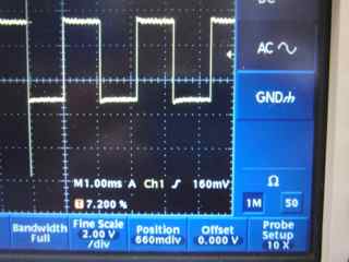
Below I show some oscilloscope traces of the signal from the LED pin, pin 8 in Arduino speak. The microcontroller is running the blink program. The scope probe is poking into the solder ball at the top of the LED current limit resistor, and is referenced to the board ground.
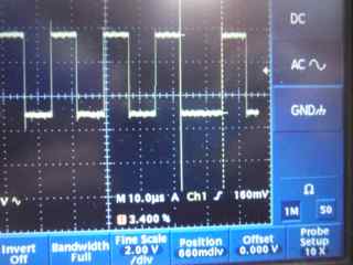
First, using a delay of 1 ms. The command is: delay(del); where del=1 The High and Low times are both 1.08 ms. (Setting the delay to 2 gives 2.15 ms).
Next, use a delay value of zero, which gives an 8 microsecond time for high and low (with sometimes a 12 microsecond duration)
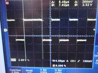
Now, eliminating the delay statement entirely, just letting the program loop between high and low, gives duration of 3.8 μs high and 4.1 μs low, with occasionally (maybe 1 out of 100) a duration of 8.5 μs, either high or low.
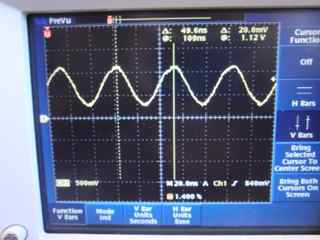
Check the clock period with the scope: For 30 periods (only three shown below) I measure 1500 ns. This is 20 MHz to within less than a percent.
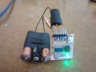
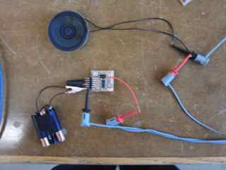
Below is a picture of the blinking thing, and on the right another output device. At blink frequencies abouve 100 hz or so the speaker is audible when connected in series with the 500 Ohm resistor (ie in parallel with the LED). When briefly attached directly to the pin, it is louder, and the micro is not damaged (not destroyed) by the near short to its output pin.
So far, I have seen that with the Arduino code I have used:
- the delay command creates pulses that are ~10% longer than expected. I does not look like the extra time is due to the LED on/off command, since the duration of the on/off states doubles when the delay time is doubled.
- when looping continuously and turning on and off as fast as the program allows, the duration is still 80 clock cycles, and is unstable. Looks like this is not the way to make precisely defined pulses! Or very fast ones.
2. Programming using shell commands on Mac OSX.
Charles Holbrow has put together a very clear tutorial on programming using command line utilities on the Mac OSX. This method uses the more standard AVR C libraries, the gcc compiler, and the avrdude programming software. Other potentially useful related links:
- Irina's page from 2011 in which she programs a LED blinker.
- tutorial on ladyada.net giving more details about setting up the AVR toolchain on the Mac.
I ran into problems as I started using the make commands. Need to back up and try again soon. Much more to do here, but something of a start was accomplished this week.
3. Class notes Nov. 30
- Taylor Levy: notes on assemblers.
- Neil shows relation between Arduino and his C code and the assembly code. Arduino blink program. Arduino calls GCC. Look at hello.arduino.328P.blink.c, hello.ftdi.44.echo.c See the assembler version of this cod in 44.echo.asm see 44.echo.interrupt. In assembly, one line turns into one code. Programming in assembly gives much more control over timing....
- See ATMEL 8 bit instruction set document for description of commands.
- term.py is a trivial terminal program. Neil repeats: if serial comm is not working, measure voltages, inspect hardware, use a scope to look for signals that match baud rate.
- sudo adduser (whoami) dialout. Or use sudo.
- David Yamnitsky made a scope.
- Comparator responds within a clock cycle. ADC can run faster at lower resolution.
- David set 8bits as the res.
- Used an op amp to set volt scale. Neil points out that a reference voltage and the onboard gain amp can be used instead.
- Used analog comparator for trigger.
- Neil: How do you use the ADC clock so that you know the origin.
- Fill a RAM buffer.
- He got 150 kS/sec.
- When making small features, may need to go to 3000 dpi on Eagle output png.
- Stick to 1/32" for vias. How to do this in Modela. Make a small circle. Use solder blob to connect vias!
- Two sided board: mill traces, cut hole, cut out. Flip over, move to corner, offset by tool diameter.
- STM32F3
- Output can be done with analog signals to LCD screens.
- Bootloader
- JFDuval: LED array
- Vinyl cutter use in CB. Keep traces ~20 mil. Check tip of blade that the depth of cut is just right for layer. Find happy range for force. Can use the white epoxy film, and vinyl cut windows to separate layers.
- In general, avoid right angles in CB's.