How to make almost anything
Will Patrick
Week 10
Output Devices
What am I building this week?
This week I wanted to create a motor controller for a wall plotting robot. What kind of wall plotting robot you might be asking? It will sort of look like a one-armed clock with a pen at the end. It will have a stepper motor controlling "theta" - the angular position of the arm - and another stepper motor controlling "r" - how far away the pen is from the center of rotation, and a solendoid to move the pen up and down.
Unipolar stepper motor driver
But I wanted to start small. So I decided to first build a couple of Neil's hello boards.
I first made the Unipolar stepper motor hello board. It was pretty straightforward. I downloaded the image files for the traces and exterior for the hello board from the course website, milled it, and stuffed the board. It looked like this:
Unipolar stepper motor board
Voila! It worked as promised.
Bipolar stepper motor driver
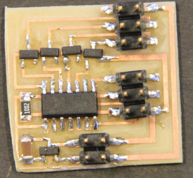
Then, the bipolar stepper:
Milled and stuffed board:
2-stepper, 1-solendoid motor controller
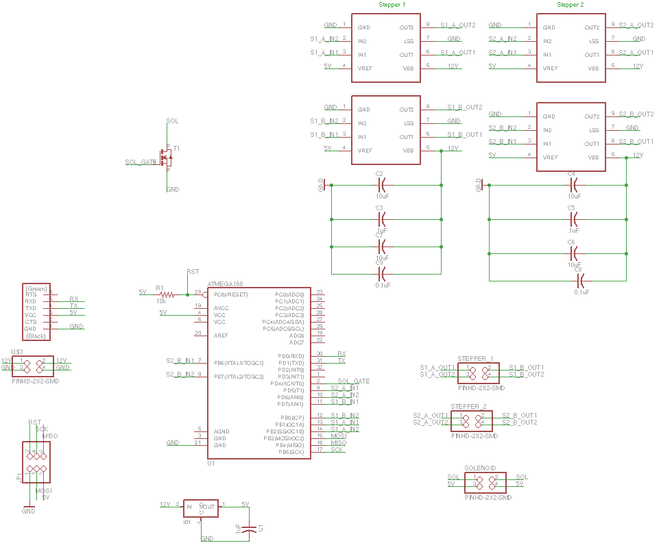
Double stepper Eagle schematic:
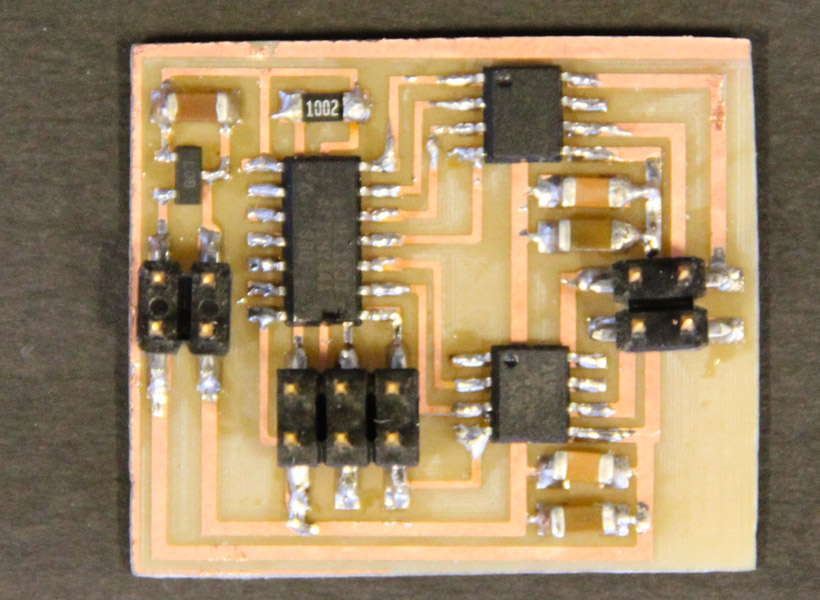
Double stepper Eagle board:
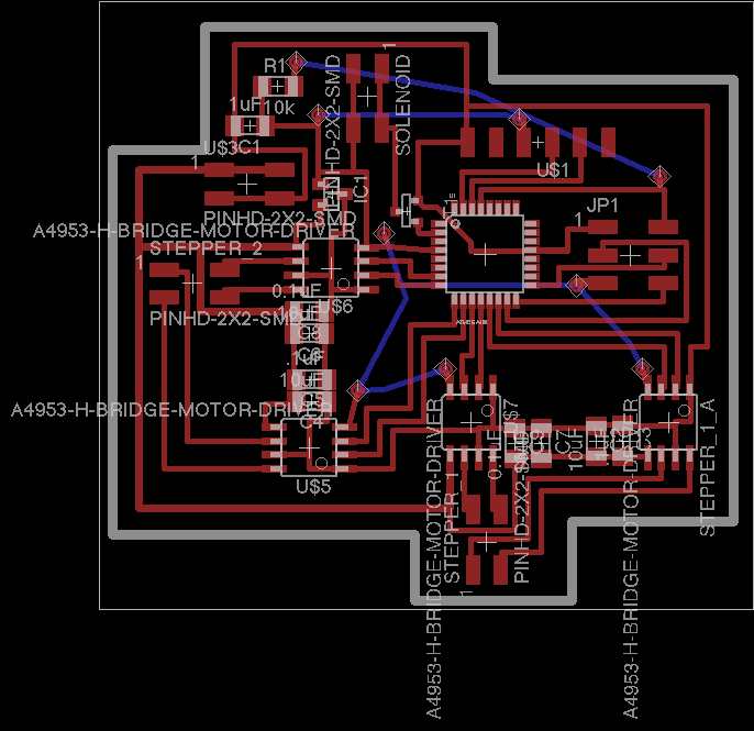
Board for two steppers
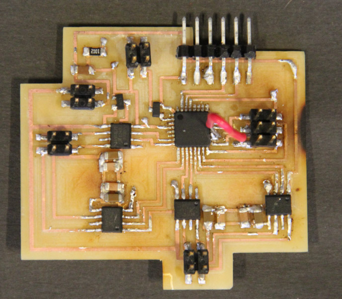
I first wanted to see if I could run the same code from the bipolar stepper motor board on this board. I made a few pin changes in the software and then flashed the board. The new motor controller performs "ok" - you can hear that there's something wrong - and the stepper is not spinning as quickly as before.
I then added the solenoid. It sort of worked. Any ideas on what's going wrong?
Next steps
The next steps for this robot is to make the mechanical system, code the motor controllers and build a software interface. Stay tuned!
Downloads
.brd file for 2 stepper + solenoid board - Download
.sch file for 2 stepper + solenoid board - Download