MAS.863

Bianca Homberg

Basics: Senior at MIT

Courses: 6-2 (Electrical Engineering and Computer Science) and 18 (Mathematics)

Primary interests: Autonomous and interactive Robotics

Week 0: Designs

Two projects: Human-climbing robot and keyboard pants.

Idea 1: Human-climbing robot

I've always wanted a pet robot that could sit on my shoulder or walk around if I put him down on the floor. It's a project that I have sketches for going back to senior year of high school (but unfortunately not ones that I have available to take pictures of). The biggest challenge that's stopped me from making one of these so far is I still am trying to figure out a good way to make legs -- I want them to be clingy and able to hold on to a shoulder, but without hurting.


clay model

Above is a clay 3D model of the potential robot, below is a 2D sketch. One of the new ideas I had when rethinking about this idea for this class was to add on a long tail -- a long, prehensile tail could serve to balance the robot and be used for stability, potentially reducing the need of the legs to have such a high degree of attachment. I'm also taking an underactuated robotics class this semester and I think it would be fun to combine the two final projects -- making the robot for this class and writing the algorithms to control a 6-legged robot with a prehensile tail dynamically and efficiently.

sketch

In thinking through the necessary steps for the project, I realized that it may be a project beyond the scope of what I can do in a final project due to the complexity, so I also wanted to go through (and start the modeling for) something that might be more achievable.

Idea 2: Keyboard pants

The basic idea is this: take a keyboard (possibly flexible, possibly stiff, possibly ergonomic) and put a half on either leg of your pants. Walking to class? It's still really easy to answer emails or work on a HASS essay. At the very basic level, the keyboard would be attached to a microcontroller which would save the data for later editing and manual parsing of what's what. It would be even cooler to either put together a prototype Google-glass like system or use Glass as an interface for seeing what I was typing and making an interface to use the keyboard as input to Glass for any application.

I've used Solidworks some in the past, but not a huge amount (and not very much for not-flat things), so I learned a bunch of things about how to do things as I went. This is the first rev -- I was going for an ergonomic keyboard design. Unfortunately, I later found out that it wouldn't let me mate my keys to it since the surface wasn't flat. In the future, I think I'm going to go for a more accurate model with cutouts for keys anyway, so that shouldn't be a problem.

backplane rev 1

Below is the updated version which I changed to be flat -- and also changed to have the proper dimensions (wider than I thought, and not as tall).

backplane rev 2

This is the key model! I figured out how to slope in the edges, which was fun -- the key took a lot less time to design than the backplane, but at this point I was also more reaquainted with Solidworks.

key

I put together an assembly (the first solidworks assembly I've made) and figured out how to mate the keys all at once instead of one by one -- one by one was taking forever. It would be neat to figure out how to import all fo the keys at once instead of one by one, though.

view 1

An angle view of the assembly.

view 2

Week 1: Press-fit Lasercutter Construction

Making lizards and knex with a laser cutter!

Laser cutter!

I had fun designing things and it's really cool to see complex shapes become real objects so quickly. I didn't realize ahead of time what proportion of the time would be designing versus actually making things -- design takes a lot longer than I'd realized. Now that I'm more familiar with some of the tools, I'm planning to make more complex designs and they'll go faster with the tools I've learned.

Wheee, lasers!

I started off the week by sketching a bunch of ideas in my notebook and then deciding which ones to start with. I still really want to make expandable cardboard wings, so I'm hoping that in a future week I'll have time to come back to this.

brainstorming!

Lizards!

The first thing I thought of for press-fit construction was escher lizards. Those images are always fun to look at, and having a tangible copy you could play with and put together would be even better. Since they're a 2D shape, I decided to try using a 2D software, Inkscape, to make them. The first two pictures show the results of the Inkscape experiments. I tried to copy the outline of an escher lizard on the internet, which didn't work very well. I knew ahead of time that it would have to be perfectly fit, but I was hoping that I could get it close enough by tracing the outline. As expected, that didn't work very well.

first rev lizards :(

Yeah, they definitely don't fit...

they don't fit very well

I also tried designing lizards from scratch, using a model of what shapes to put where that I found online -- these ones are based off of a hexagon. I made another one in Inkscape, but I coudln't see how to force points to be the same point, and essentially wound up copy/pasting shapes and eyeballing symmetry. I didn't expect those to work at all -- but they did (they're the largest size of lizard). I wanted to make a more precise fit, so I went back and redesigned lizards in Solidworks. Getting to add dimensions and specify points were coincidental made it go a lot faster.

lizards on solidworks

Three sizes of lizard! The bottom two are identical shapes designed in Solidworks, just scaled; the top ones are the ones I manually designed in Inkscape.

3 sizes of second rev lizards

And stacked!

stacked lizards

A closeup of the fit -- they fit nicely together, but aren't quite pressfit. For next time, I'd need to work on adjusting the laser cutter offset to make it print on the outside. I was using CorelDraw to print and I couldn't see a way to do it, but I'm hoping to figure that out and make a second rev at some point.

lizard closeup

They line up nicely enough that you can see the inner lizard shape:

lizard ring

Cardboard Knex

Since the main goal for this week was to make a 3D construction kit, I wanted to make something besides lizards. One of the construction kits I played with as a kid was Knex, so I wanted to take that basic idea and laser cut it. One of the cool things about Knex is specifically that you take 2D pieces and interlock them to make 3D pieces, so I replicated that functionality in my pieces. The posts don't work the same way -- interlocking the 3D pieces cuts off one direction you can stick posts. Other than that, it's basically equivalent to Knex!

There's a little more flexibility in how you connect these pieces because they're pressfit instead of clicking into one locked orientation and they're more interchangeable about what you connect -- some of these the constructions below couldn't be made simply with Knex.

Original sketches:

sketch

This time, I didn't bother with Inkscape and went straight to Solidworks.

solidworks

Laser cutting these was very straightforward since I'd already figured out the workflow with the lizards. I got the pressfit size right the first time entirely by accident, so I kept it. I tested with and without notches and determined that notches were, in fact, easier to use, so I added those to all of my files and printed. I left all of the parts on my floor's kitchen table for the past couple days; here's some of the stuff that people stopping by put together!

Construction toys on kitchen table = friends take a pset break.
random putting parts together
Why not add lizards?
A square
more fun with construction

Edit!

I did go back and make cardboard wings!


Week 2: Electronics Production

Milling a PCB, soldering it, plus some website making adventures.

Milling the PCB

Milling the PCB was quite straightforward with the fab modules. There were a couple changes that needed to be made to make our machine work (using sudo and changing USB1 to USB0), but those were well documented here. The first time I tried to make the board, I accidentally used a too-wide blade, and there were no traces left, so it was unusable.


The second rev (with the 1/64 blade for traces, 1/32 for the outside) went a lot better.


Other than using the wrong blade the first time, this process went quite quickly and was straightforward. I didn't expect it to be so quick. I just started learning about PCB design this summer and at my internship we had used external board fabrication. This method wouldn't let me make the multi-layer boards I designed there, but for simple things, this definitely seems like a good option with a fast turnaround time!

Soldering the PCB

I've been soldering for a long time, so this part was entirely straightforward. I'm a firm believer in the use of lots of flux -- it makes the joints look a lot nicer and makes the solder flow better. The method I normally use for placing surface mount components is to put flux over the pads, put a little solder on one pad, place the part, make sure the part is flat, solder the other side, and then go back to the first side if necessary. All of the components we had were pretty big, so nothing caused problems.


Making the Website

I've never made more than a simple HTML website before or used CSS or Javascript. This week, I put some time into making a slightly fancier website -- and learning the basics to hopefully make it even cooler over the coming weeks.

I wanted to share some of the tools that I used that I found really helpful getting started. I had a great friend who helped me out showing me where to start, but without knowing where to start, it's hard to even know what to Google for.

Less is a tool for writing code that compiles into CSS. I haven't worked enough with either Less or CSS to know what cases it's useful in, but I've been told that it's useful for managing larger projects without getting weird bugs cropping up. I don't think it's super relevant for what I have so far, but I want to improve the site too over the course of the class, and it seems like a good idea to start off with good practices.

jQuery is a Javascript library which helps you make animations in the browser. For this version of the site, I used it to change colors of a box when I hover over it and to expand/contract the different sections for each project.

Codepen is a cool site -- it'll let you mock up some html, CSS, and Javascript all together. I used it to do some testing with html, Less, and jQuery. It was a great sandbox to figure out how things worked without having to continually recompile Less into CSS and without needing to continually refresh my browser. It also warns you about syntax errors so you know to fix them. It's probably slightly too clunky to design your whole site in -- it only lets you make one page, at least for the free version -- but you can design everything there and then copy/paste the code out for your final website.

Week 3: 3D Printing

Android gear necklace, 3D scanning Pooh and a friend, 3D printing the scanned Pooh.

Android gear necklace

I wanted to design something small, cute, and with internal parts that moved. I decided on making a steampunk-esque necklace in the shape of a Google Android with internal gears. The final model had 7 independent gears, each sized differently. I designed the outer case first, making the shape of the android, with insets for eyes. I also added appropriately sized shafts for each of the gears. This made the main body for the necklace.


Next, I made each of the gears. Each of the gears was very similar, so I just copied the model and made slight edits to the values of the original sketch. Most of the gears I built in 3 pieces: the first original circle, the outside gears (made with a circular pattern in the sketch) and finally a hole in the center. Two of the larger gears also had holes so that we could see through them to the gears beneath them. They were a separate sketchthat was repeated with a circular pattern.


I learned how to put holes in a curved surface in Solidworks this week. You have to first create a plane perpendicular to the surface you want to cut through, then make the cut extend through the curved surface. I used this to make the two holes at the top where the necklace cord will go through.


Final printed model.


The final model didn't come out as well as I'd like. Unfortunately, I didn't get the piece back until after the second 3D printing run had happened, but I'm planning to revise the model to rerun next week. One of the gears had accidentally been placed too low, so it merged with other parts and wasn't free to spin. Beyond that, it turns out that I'd left too much space around the shafts -- a 1mm margin left far too much slop. I'm planning to reduce that distance to .3 or .4 mm on either side -- just slightly above the precision of the 3D printer. Also, one shaft was too narrow, and broke off before I even saw the piece. Some of the gears were also made slightly too small and were too far apart from each other to mesh well, even without the slop. I need to increase the size of these gears, and decrease the size of the one gear that was too close to the edge and was attached to the edge. This is the final model after I tried to disconnect the gears where they'd been improperly attached.


3D Scanning & Printing Pooh

Scanning was incredibly finicky. It took numerous tries to figure out the right distance and settings with which to scan an object. About 3 feet away worked the best. The pictures below show 2 failed scans, followed by a working raw scan and then the cleaned up version of the working raw scan. I couldn't manage to get a scan 100% of the way around the model, but I did get the front half -- enough to get a scan that was obviously recognizable as Pooh.


I spent a while cleaning up the back of the model to make it as flat as possible, then I 3D printed it on the Up printer. It didn't come out quite as well as I'd hoped -- the colors on the scan definitely helped it look more like Pooh. The super small size I decided to print it at didn't help either. But it still came out pretty well!


Scanning a Friend's Head

The software worked a lot better at scanning a head. I still wound up losing tracking partway through, but I got a lot farther before losing it and the scan didn't wind up making any obvious mistakes. I didn't actually want a 3D printed model of my friend's head, so I didn't bother to repeat the scan or clean it up in order to print.


Week 4: Make Something Big

Learning to use a large format CNC, making a laptop stand.

Learning to use a large format CNC

We had some issues figuring out how to use the shopbot at first. Our bit wasn't tightened enough, so it loosened and came down -- this caused us to cut 1 inch deep into the board below the OSB and made the shopbot make lots of squeaky noises. A very helpful person helped us clear the wood shavings out of the collet so that it could tighten around the bit correctly. Once that was set, the milling went much better.

I also forgot to cut internal parts the first time through -- If I'd cut internal parts first, I would have been able to resume after running into the bit problem, but this way, I had to restart.

Unfortunately, the OSB had a rather nasty edge. It's good enough for a prototype, but I'm planning to remake this to actually use out of something nicer that will have a better finish.


Solidworks Design

I designed a laptop stand to put on my new desk in my lab. I designed the front to have a cute robot, my name, and my lab's name -- all to be cut at a smaller depth as a decoration. Unfortunately, since the OSB had such a nasty finish, I decided not to go ahead with cutting out the pattern since it would be all splintery and hard to see anyway.


This is the design for the finished box. There's a tray in the center for holding the laptop (my laptop folds backwards). This tray is removable so that I can store simple office supplies underneath the tray. I'm planning to lasercut a cardboard organizer for the final version. There's also a backstop for the laptop, and the top tray will have an inset so that the keys and trackpad on the laptop don't get hit by accident.

There are two side pockets for folders/paper storage on one side and cables on the other. The side holes are allowing cords (to my keyboard, mouse, etc) through in a clean, organized manner.


Actual box

Here's the finished box! I forgot to put T-bones on the cuts for the inside supports, so I needed to more sanding. Since I'm planning to remake the box anyway, I figured it wasn't worth the time to sand. I unfortunately couldn't recut the pieces since the Shopbot was too backed up with other people needing to use it. The T-bones are necessary since the round mill can't make a perfect corner -- in order for press fit tabs to work, the end mill needs to go a little past the corner to leave space.


I did manage to make one of the inside pieces fit after a lot of sanding, but it was very hard to fit the front piece on after. Next time, I'll probably make my tabs a hair larger too to make it easier to fit, in addition to making sure to put t-bones on all parts..


Finished box from another angle.


This is the inside section stuck together, demonstrating the tray and the backstop. I didn't cut the pocket on the tray due to other people needing to use the Shopbot machine and the tray not being necessary for the prototype proof of concept.


UPDATE: With the addition of a hammer, I got all of the parts to pressfit together! Updated photos of the stand with the laptop. Hopefully I'll have a chance to paint it soon and then move it to my desk!


UPDATE #2: I painted this! It's ready to be used!


Week 5: 3D Electronics Design

Designing an updated hello world board, plus fabricating it.

Designing the board in EAGLE


I designed the board using EAGLE. I used Altium this summer, and I like it a lot better, but unfortunately MIT doesn't have an Altium licensce -- just like the class has a Solidworks licensce, maybe next year could get an Altium licensce? In any case, since I know a lot more techniques of what I want to do now, making the schematic went a lot better than the last time I used EAGLE, especially with the fab library. I didn't have to design any compnents at all, since everything I needed was already included. Below is my final schematic. In addition to the basic helloworld board, I added a reset button which will pull the reset button on the ATiny board low. I also added two LEDs -- one will turn on when the board is powered; the other can be controlled from the ATiny.


Based on this schematic, I routed the board. This is the top layer routing. I may have been able to make this board work as a single layer board, especially with a jumper or two, but since most more complex boards need more than 1 layer, I wanted to experiment with making a multi layer board with vias during the hand fabrication process. I want to be able to design boards so that I can mill them to test them out but so that if I want to have a more polished board, I can send the same design out to a fabrication house. So, I made the top plane a VCC plane and the bottom plane a GND plane. I routed all of the traces on the top plane, and had four vias (the traces into nothing) to the bottom plane. (Tip: to make planes in EAGLE, use the Polygon tool. To set it to a specific net, though, you need to separately use the naming tool. Use the ratsnest command to make it floodfill appropriately.)


Milling the board


In order to mill it out, I inverted the schematic. I set the command to mill out all empty space (ie, all of the black space). This cut spaces between traces and pads, but left the large polygon intact.


I added an outline to my board, as well as the four via holes. I made this file manually in Gimp based on the previous board design to make sure it was aligned correctly. I wound up changing my board slightly, so I wound up having to adjust my zeroing position when I milled it in order to make it line up right -- luckily, all that running the mill incorrectly got was a couple shallow holes in places that didn't cause a problem.


I had some problems using the online fab modules to connect with the Modela. At this point, the causes of this error have not been resolved yet. I just switched to using the command line fab modules, which worked a lot better.


The final milled board! (Note the couple extra circles that aren't cut through that shouldn't be there).


Double sided board

In order to make my double sided board, I took a piece of the copper for the vinyl cutter and stuck it on the back. For a more complicated design, I could have cut the traces out of the vinyl cutter and put a more complicated circuit on the back and made the vias the same way.


Then, after trimming it, I punched holes through the back at each via.


This is a close-up of a finished via. I took a small piece of wire, stuck it through the via, and soldered it on one side, then the other.


Soldering the board

Final board with all components (and all vias!).


This is what the vias look like from the back. They're pretty ugly, but they could be made a lot smaller if necessary if there was limited space or they needed to be attached to a trace -- the second side is actually easier to solder than the first, so if I were redoing this I might solder to the open/easier side first. I also might make the vias before soldering all of my other parts so it's easy to flip the board upside down.


Week 6: Molding and Casting

Chocolates and a soft robotic hand.

Soft robotic hand molds

I designed some molds for a soft robotic hand in Solidworks, based on some work my labmates did. It expands their design from a single finger into a full starfish-shaped hand with 6 fingers. Due to not yet getting 3D printer time, I haven't been able to complete this model yet. Since there's an entirely contained object, this must be lost-wax cast.


Chocolate molds

I designed two molds: one with a Google Android and a generic robot, the other with two minions from Despicable Me. I designed them in Solidworks and 3D printed both molds. I did a good job of making sure corners were rounded, but I should have made the whole structure angled to make it easier to take the chocolates out of the molds. I also should have made the arms wider -- they fall off a lot. For food-safe material, I used Smooth-On 940.


Milling in wax

The previous molds were 3D printed, since the Modela was broken over the weekend. To do 3D toolpath planning, I used the (compiled) fab modules on the Modella on a simple example to make sure I knew the procedure. I designed a simple lego brick shape in Solidworks and milled that.


Edit!

I went back and made a soft mold out of the wax mold.


More edits!

I haven't had a chance to mold the six-prong robotic finger yet, but for my research, I've designed and casted a lot of robotic fingers in molds! Various pictures are below (and the process is not fully documented because the research this is based on isn't yet published).


Week 7: Embedded Programming

Debugging serial communication + blinky lights.


The assignment for this week was to program our echo board. In addition to the echoing capability, I had three additional things added to my board: an LED to turn on when the board was powered, an LED that could be controlled via a pin on the ATiny44, and a button which would reset the board. Having the "board power on" LED was great -- immediately after plugging the board in, I knew that at least it was powered and one thing was working. At first, I had the wrong header on the board which shorted all of the pins together, but once that was fixed, my echo board was fine.


Initially, I had problems programming my FabISP -- I was trying to use the standard AVR MKII ISP, which doesn't work in Ubuntu without some hacking (I tried a few things on the internet, but didn't get it to work) and in Windows, I was having driver issues. After getting my FabISP programmed separately, though, it worked great in Ubuntu with avrdude. After downloading the source and make files in the same directory, I ran the command "sudo make -f hello.ftdi.44.echo.c.make program-usbtiny" to program the board.

I found it straightforward to turn the light on and off. I looked at my schematic/the ATiny44 datasheet and figured out what pin it was on. Then, I used the following code to affect the light:

// in the beginning of the file, with all of the other defines
#define led_pin (1 << PA7) // this sets the LED pin number to pin PA7
#define led_port PORTA // Because of the A in the pin number, we know the LED is on port A
#define led_dir DDRA // this will be used to set the LED pin as an output pin

// in the main block of code to be executed
set(led_port, led_pin); // this turns the LED on (using the set macro already defined)
_delay_ms(500); // delay for half a second
clear(led_port, led_pin); // this turns the LED off (again using macros)

That's all that's necessary to program an LED light to blink! I also had to debug my button not working, but that turned out to be a circuit error: I shouldn't have put the pull-up resistor on the board -- it caused the button to be unable to pull the reset pin low enough to trigger a reset. Depopulating the resistor fixed the problem!


I ran into a lot of issues trying to make the echo functionality work. I did some debugging on the oscilloscope to find the minimum pulse. One thing I'd do differently next time I make a board is plan to have easy attachment points for measuring signals on the oscilloscope. I wound up soldering on a wire to be able to easily measure ground, but it would have been nice to have an easier attachment point. It was always about 3x longer than what was appropriate given the baud rate -- it turns out I hadn't set the fuses on the board to use the external 20Mhz crystal instead of the on-board 8Mhz clock. After figuring out this was the problem, I needed to run a command to see the fuse values and another to reset it.

Reading fuse values: sudo avrdude -p t44 -c usbtiny -U lfuse:r:-:h -U hfuse:r:-:h This reads both lfuse and hfuse values; for the default echo board configuration, only the lfuse value actually matters.

Setting fuse bits: sudo avrdude -p t44 -c usbtiny -U lfuse:w:0x7E:m This sets lfuse to 0x7E, which we need for the 20Mhz external clock.

If this didn't solve your fuse bits problem, you may find one of the following websites useful. I couldn't use either of their commands directly due to the different chip I was using, but it might be useful: http://blog.louic.nl/?p=161, http://riktronic.prismaticmedia.com/?p=15.


After debugging fuses, it echoed great! There's still a line wrap issue in terms of character encodings (presumably how I'm representing things on PuTTY), but the important part is to get serial communication working, which I did. Note that in between the 'abcd' and 'test' strings I pressed the reset button on my board which I added -- no need to unplug/replug the board.


The final working setup!


Week 8: Composites

Composite sled!


To start off, I milled a mold out of styrofoam! This took forever, since the mold was pretty deep. However, I used scrap pieces for the front, so the mill spent a lot of time cutting air. One problem I ran into was that the mill bit was too short, so for subsequent passes, the chuck hit the side of the foam. I had originally intended the mold to have longer sides, and have vertical handles (instead of the horizontal handles I wound up with). I couldn't keep them, though, since the mill kept crashing into them. I made the 3D toolpath with Mastercarve 3D. I'm not sure there's a good way to prever the mill from hitting the material, and I'll make sure to take that into account in the future. Even though it'll mean even more milling time...


I cut a lot of pieces of burlap! It wasn't quite wide enough, so each layer had two pieces I had a minimum of 5 layers in any location, more in the center, and I also put a brace piece at the top and bottom going the other direction. The handles were also further reinforced.


Initial vacuum sealing. We ran out of mastic tape, so I used masking tape to try and close the rest of it. I thought it was fine since it was sucking, but I should have checked the psi -- it was only at 4psi! Luckily, another classmate noticed it, and she taped it up with duct tape. That worked a lot better, and the bag got up to 25 psi. Apparently, the vacuum compresser is a lot happier at 30psi -- it smoked a lot at 25psi.


The white release fabric (which was on the top) worked great. The sections that had both the white and red release fabrics also worked fine (though the red fabric left a bit of weird residue). The sections that just had the white release fabric was terrible. :( The little holes in the fabric let the breather fabric go through and attach to the board. I'm going to need to go back and pull all of the remaining fluff off. I heard a suggestion to put release fabric on the other side too -- that was probably a good idea.


We were told to paint the styrofoam mold, and that that would be sufficient for getting the part out of the mold. I did not find that to be the case. I had to pry all of it off. This took a lot of hammering, prying off with a knife, using the back of the hammer like an axe. I did learn that if you email your dorm asking if any frustrated psetters want to have a go at it, you'll get some people to come down and finish it off for you! Given the beating this poor sled took to get out of its mold, I am entirely unworried about its structural stability. If it can survive that, it can survive anything. Below is the partially excavated sled and a huge mess.


The finished sled! All that's left to make it hill-ready is a couple coats of paint and a little remaining de-fluffing!


Edit!

I went back, sanded, de-fluffed, and painted the sled. The finished product is now slope-worthy!


Week 9: Input Devices

Flex and force sensors on a soft robotic hand.

Designing the PCB

The basic circuit is pretty simple -- the RC resonator, FTDI connector, ATiny45, and six pin connector are all in the default configuration. For the two input pins, I used an op-amp to buffer the output values. This wound up increasing my debugging time, but the op-amp stabilizes the voltage and gives a more robust output value. It was the recommended circuit design for the flex sensor given in the datasheet.


I didn't quite manage to make it a one layer PCB. While possible, it required too many traces too close together underneath the microcontroller. Instead, I made it as close as I could, and added three jumpers to complete a few connections.


Making the PCB

This is the force sensor I used. The datasheet is available here. It's a pad which measures the force by which it is pressed down, from .2N to 20N. This is useful in the context of the soft robotic hand for doing force control -- for instance, picking up an egg is a very gentle task that needs only a slight amount of force, while still ensuring that there was enough force to actually pick up the object.


This is the flex sensor I used. The datasheet is available here. The flex sensor will be useful for figuring out the final position of the finger. The pressure gives some indication of the position of the finger, but if the finger hits an object and conforms, its shape will be different.


After lots of milling, soldering, and debugging, this is the final board! Some mistakes I made I won't make in the future: make sure to mill with a sharp endmill, otherwise it won't work very well and you'll need to go back over it a bunch of times. Make pads for jumpers a little bigger, so they pull up less. Prepare ahead of time for cuts you'll need to make by hand.


Putting the sensors on a soft robotic finger

I got both of the sensors working (individually) using the same code as was on the website for the thermemometer, since all it does is read in the data from a certain port. Next week, when I combine this with my output code, I will edit the code to read both at once. I will attach the sensors more securely by adding a layer of oomoo. I tried hot glue and krazy glue, but neither of those would stick to the silicone. For now, an approximate result can be achieved by zip tieing the flex sensor onto the finger.


Week 10: Output Devices

Servo for turning off an electric blanket.


My goal with this project is to have a small servo which can turn off my electric blanket. By setting a timer, the board will wait twenty minutes, then activate the servo. The big challenge here is that the first rev board drew too much current -- I wouldn't be able to power the board for very long on battery power. For next week, I have several edits that I am going to incorporate to reduce the power usage of the board, in addition to allowing the board to be activated via bluetooth.

Designing the PCB

I based the design of the board off of the servo example board online. I find it useful to have a light that indicates that the board has power (especially since this board had a voltage regulator rather than plain input power) to help debug. This was actually really useful -- there was initially a missing trace that somehow wasn't transferred from the schematic to the layout in Eagle, which was easy to debug since I could immediately tell something was wrong with the power light off. If I had to do this again, I'd put in a through-hole component that allows you to screw power wires on. I wound up doing this anyway by soldering that part to the top of my input pins, but it would be easier to just make directly.


Fabrication

After debugging the two missing traces, programming the board was straightforward with the software servo example on the fab website. As before, I did have to change the fuses since I was using an external timing source. This is a picture of the working setup. I programmed it exactly the same way I programmed the input board and the echo board, no changes.


Changes for next week

Running the servo worked fine, but the board draws 120mA sitting and up to almost an amp when the servo is running. For next week, I am going to use a bluetooth low energy chip, so the board will only turn on when a signal has received. I will also use a more stable and higher capacity power source (normal AA batteries instead of a 9V batteries) -- this will have the side benefit of not needing the voltage regulator. I will also put the ATiny44 into low power/sleep mode when it's not being used. With this, I'm hoping to have a self-contained circuit that won't need to have a battery changed more than once a month.

Ideally, this will become part of a larger project where one central unit sends out commands to various low-energy bluetooth devices around my room. I can send text messages to that central unit to pass on commands.

Week 11: Networking

Revised servo board to be controlled via bluetooth. (Not in class for Thanksgiving today).


Plan

My eventual plan is to have a three part network. I want to be able to use my phone to send a message over wifi to a hub in my room. This hub takes in the message, interprets it, and then sends out a corresponding command over bluetooth. To start, this will just be the servo mechanism I worked on last week. Eventually, I'd like to have a bunch of small circuits in my room that the hub can connect to and control remotely.

Status as of 9am 11/26: I spent a long time just being able to download my code to the board within the Arduino environment with the HC05 library. I haven't finished debugging the actual use of the Bluetooth module yet.

Board design

I designed the two boards in Eagle. The hub board (shown first) has both the bluetooth connector and the wifi module. To start, I'm only going to work on connecting the bluetooth connector. Next time, I should add more debugging features, like a serial port to FTDI. I soldered on an ad-hoc one for debugging, but it would be great to have it already built in by default. I'm really glad that I decided to use the screw-in connection for power -- it's so much easier than just using a default header.


For the outpost with the servo, I adapted my servo board from last week, adding on a bluetooth sensor and some debugging LEDs. Had to add in a lot of 0-ohm resistors to make the board design work -- such a pain. I wish there was a better way.


Fabrication

Fabrication was fairly straightforward. It was a little tougher to solder the Atmega328p than the Atiny44/45, but still manageable. It's still frustrating to not be able to make 2 or more layer boards easily, but that's more of a design challenge than a fabrication challenge. Milling mostly worked fine, though I did run into an issue with one of my board outlines where the fab modules calculated an accurate looking path but then sent a path to the Modela of just driving the spindle straight up and stopping. Luckily, the board was big enough that I didn't need to bother to cut it out. Other than that, nothing special this week on fabrication.

Debugging

I had a lot of trouble downloading to the board. For all past weeks, I've used the default c code and makefiles or slight variations thereof. I never needed any Arduino libraries, so I never got the Arduino environment up and working. I tried a bunch of things in both Linux and Windows. In Linux, the fab ISP doesn't show up as a USB port for some reason. Downloading code using avrdude works fine, though -- I'm not sure how it figures out what port to use, but it figures it out. However, the Arduino IDE complains about not being able to find the ISP. Switching over to Windows, I tried serveral drivers, checked that SecureBoot was disabled, and disabled driver signature checks, but I couldn't get the drivers to install for the fabISP. So I switched back to Linux. I tried compiling all of the Arduino libraries by hand, but wound up running into problems there when trying to use the additional HC05 library. (Other than not including directions for that, the website was on the whole rather useful: https://www.ashleymills.com/node/327).

Eventually, I found a workaround. I imported the HC05 library into the ArduinoIDE. I compiled the Arduino code for one of the Arduinos with an Atmega328p on it. However, I couldn't upload it using the IDE, so I just ran the Verify/compile. This places the resulting compiled files (and in particular the hex file) in a folder inside /tmp. I went to /tmp, went to the appropriate folder (build, followed by a bunch of numbers, ending with .tmp), and from there downloaded like I have in the past using avrdude. Took much longer to find this workaround than I would have liked, but this ultimately works fine.

Picture of my setup/boards:


Next steps: hook up an FTDI cable to be able to read the serial debugging output for the HC05. Find more documentation; figure out how to connect my computer to the bluetooth module first and then figure out how to connect the bluetooth modules to each other.

Todo

At this point, I've finally gotten programming working to the Atmega328p chip with compiling the HC05 library. I am in the process of debugging the bluetooth communication. It appears to be hooked up correctly, since it is blinking at the twice-per-second rate that corresponds to waiting for a connection. I'll continue working on this over the next week alongside of Week 12's assignment.

Update

I kept working on this, but continued to have trouble making the bluetooth module work. I think it mayhave been problems with using SoftwareSerial.h through Arduino (especially given the hackish nature of how I downloaded arduino code). I read the outgoing serial messages and used an oscilloscope to figure out timing delays (I had to change the clock divider as well as the fuse bits), but I still kept getting garbage passed to the computer, no matter what baud rate I tried. I could connect to the bluetooth board from my phone as well and tried to run an echo program, but got nothing back. The next thing I need to try is using just avr without Arduino and also try communicating to the board via hardware serial, just to make sure that nothing got damaged.

Week 12: Interface Programming

Some GUI edits and ROS integration.


Editing the GUI to show two sensor readings

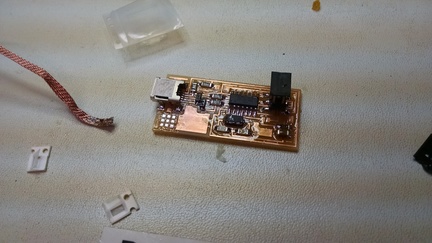
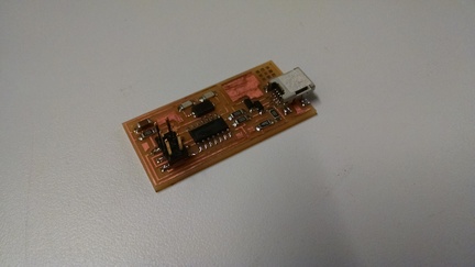
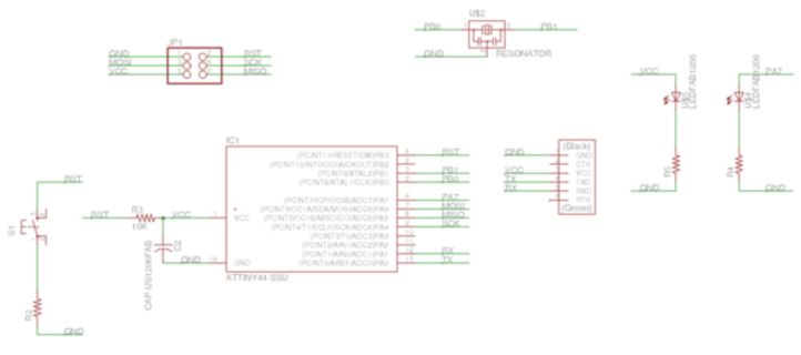
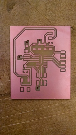
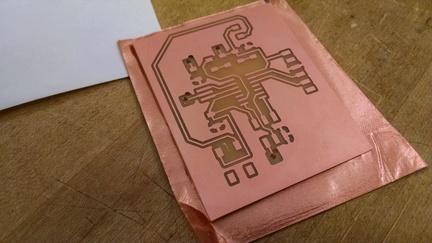
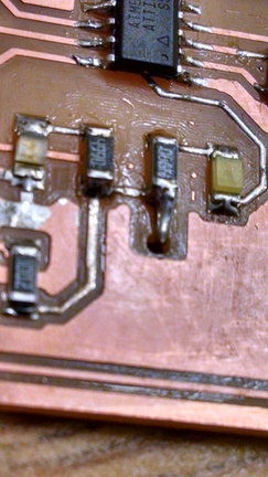
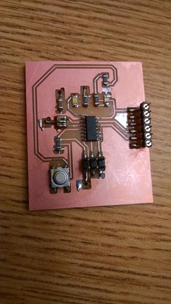
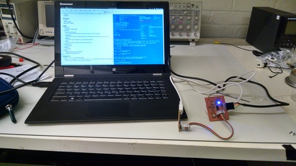
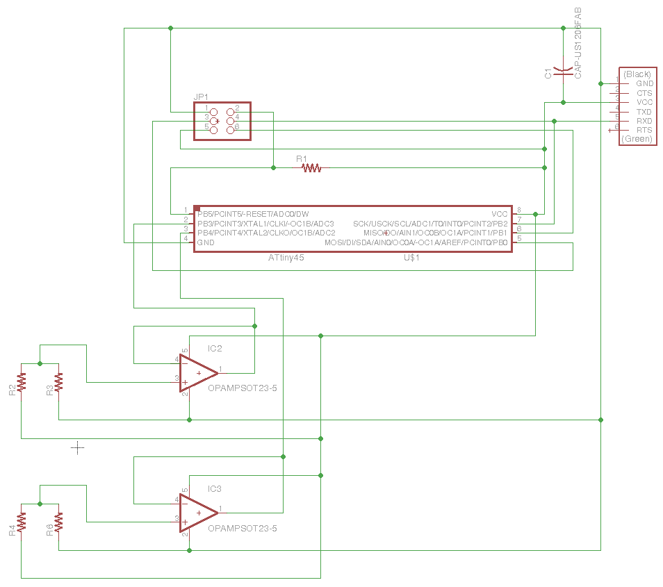
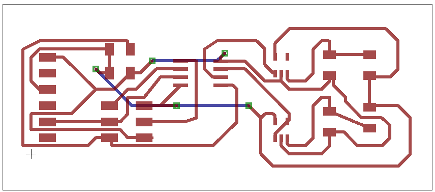
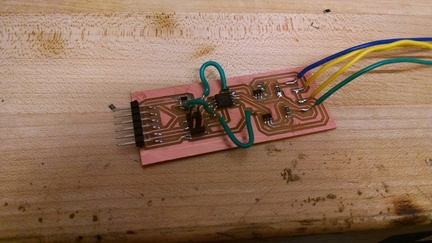
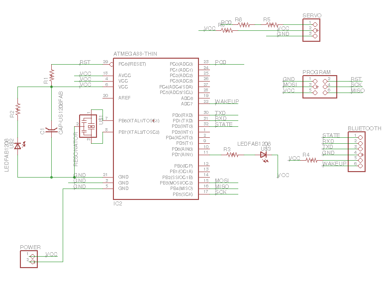
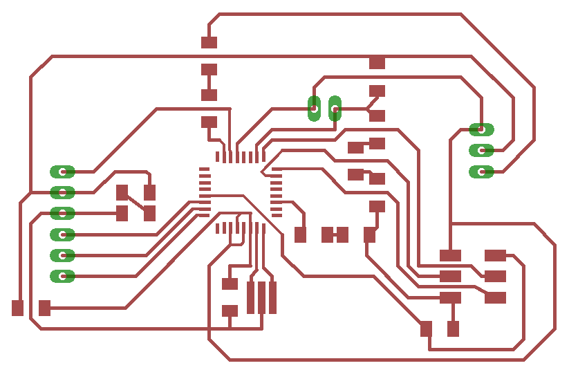
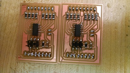
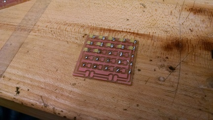
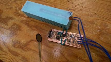
During input devices week, I made a board with two sensors. In order to view both sets of data, I switched the serial output between the two relevant pins in the program and reprogrammed the ATiny44 in order to see the other sensor output. This week, I edited the code on the board and edited the GUI to show both data points at once. I tested it by activating each sensor independently and seeing the response. It took a little fiddling with parameters and figuring out how Tkinter works, but ultimately was relatively straightforward. Code on the ATiny44:

#include 
#include 

#define output(directions,pin) (directions |= pin) // set port direction for output
#define set(port,pin) (port |= pin) // set port pin
#define clear(port,pin) (port &= (~pin)) // clear port pin
#define pin_test(pins,pin) (pins & pin) // test for port pin
#define bit_test(byte,bit) (byte & (1 << bit)) // test for bit set
#define bit_delay_time 102 // bit delay for 9600 with overhead
#define bit_delay() _delay_us(bit_delay_time) // RS232 bit delay
#define half_bit_delay() _delay_us(bit_delay_time/2) // RS232 half bit delay
#define char_delay() _delay_ms(10) // char delay

#define serial_port PORTB
#define serial_direction DDRB
#define serial_pin_out (1 << PB2)

void put_char(volatile unsigned char *port, unsigned char pin, char txchar) {
   //
   // send character in txchar on port pin
   //    assumes line driver (inverts bits)
   //
   // start bit
   //
   clear(*port,pin);
   bit_delay();
   //
   // unrolled loop to write data bits
   //
   if bit_test(txchar,0)
      set(*port,pin);
   else
      clear(*port,pin);
   bit_delay();
   if bit_test(txchar,1)
      set(*port,pin);
   else
      clear(*port,pin);
   bit_delay();
   if bit_test(txchar,2)
      set(*port,pin);
   else
      clear(*port,pin);
   bit_delay();
   if bit_test(txchar,3)
      set(*port,pin);
   else
      clear(*port,pin);
   bit_delay();
   if bit_test(txchar,4)
      set(*port,pin);
   else
      clear(*port,pin);
   bit_delay();
   if bit_test(txchar,5)
      set(*port,pin);
   else
      clear(*port,pin);
   bit_delay();
   if bit_test(txchar,6)
      set(*port,pin);
   else
      clear(*port,pin);
   bit_delay();
   if bit_test(txchar,7)
      set(*port,pin);
   else
      clear(*port,pin);
   bit_delay();
   //
   // stop bit
   //
   set(*port,pin);
   bit_delay();
   //
   // char delay
   //
   bit_delay();
   }

int main(void) {
   //
   // main
   //
   static char chr;
   //
   // set clock divider to /1
   //
   CLKPR = (1 << CLKPCE);
   CLKPR = (0 << CLKPS3) | (0 << CLKPS2) | (0 << CLKPS1) | (0 << CLKPS0);
   //
   // initialize output pins
   //
   set(serial_port, serial_pin_out);
   output(serial_direction, serial_pin_out);
   //
   // init A/D
   //
   ADMUX = (0 << REFS2) | (0 << REFS1) | (0 << REFS0) // Vcc ref
      | (0 << ADLAR) // right adjust
      | (0 << MUX3) | (0 << MUX2) | (1 << MUX1) | (1 << MUX0); // ADC3   1 0 for ADC4, 1 1 for ADC3
   ADCSRA = (1 << ADEN) // enable
      | (1 << ADPS2) | (1 << ADPS1) | (1 << ADPS0); // prescaler /128
   //
   // main loop
   //
   while (1) {
      //
      // send framing
      //
      put_char(&serial_port, serial_pin_out, 1);
      char_delay();
      put_char(&serial_port, serial_pin_out, 2);
      char_delay();
      put_char(&serial_port, serial_pin_out, 3);
      char_delay();
      put_char(&serial_port, serial_pin_out, 4);
      char_delay();

      ADMUX = (0 << REFS2) | (0 << REFS1) | (0 << REFS0) // Vcc ref
	| (0 << ADLAR) // right adjust
	| (0 << MUX3) | (0 << MUX2) | (1 << MUX1) | (1 << MUX0); // ADC3   1 0 for ADC4, 1 1 for ADC3


      //
      // initiate conversion
      //
      ADCSRA |= (1 << ADSC);
      //
      // wait for completion
      //
      while (ADCSRA & (1 << ADSC))
         ;
      //
      // send result
      //
      chr = ADCL;
      put_char(&serial_port, serial_pin_out, chr);
      char_delay();
      chr = ADCH;
      put_char(&serial_port, serial_pin_out, chr);
      char_delay();


      ADMUX = (0 << REFS2) | (0 << REFS1) | (0 << REFS0) // Vcc ref
	| (0 << ADLAR) // right adjust
	| (0 << MUX3) | (0 << MUX2) | (1 << MUX1) | (0 << MUX0); // ADC4   1 0 for ADC4, 1 1 for ADC3


            //
      // initiate conversion
      //
      ADCSRA |= (1 << ADSC);
      //
      // wait for completion
      //
      while (ADCSRA & (1 << ADSC))
         ;
      //
      // send result
      //
      chr = ADCL;
      put_char(&serial_port, serial_pin_out, chr);
      char_delay();
      chr = ADCH;
      put_char(&serial_port, serial_pin_out, chr);
      char_delay();

      }
   }


The relevant change in the Arduino code is the resetting the value of ADMUX and sending the second result each cycle.

For the python output program, it appears as follows:

from Tkinter import *
import serial

WINDOW = 600 # window size
eps1 = 0.5 # filter time constant
filter1 = 0.0 # filtered value
eps2 = .5
filter2 = 0

def idle(parent,canvas):
   global filter1, eps1
   global filter2, eps2
   #
   # idle routine
   #
   byte2 = 0
   byte3 = 0
   byte4 = 0
   ser.flush()
   while 1:
      #
      # find framing 
      #
      byte1 = byte2
      byte2 = byte3
      byte3 = byte4
      byte4 = ord(ser.read())
      if ((byte1 == 1) & (byte2 == 2) & (byte3 == 3) & (byte4 == 4)):
         break
   low = ord(ser.read())
   high = ord(ser.read())
   value1 = 256*high + low
   
   filter1 = (1-eps1)*filter1 + eps1*value1
   x = int(.2*WINDOW + (.9-.2)*WINDOW*filter1/1024.0)

   low = ord(ser.read())
   high = ord(ser.read())
   value2 = 256*high + low
   
   filter2 = (1-eps2)*filter2 + eps2*value2
   y = int(.2*WINDOW + (.9-.2)*WINDOW*filter2/1024.0)

   
   canvas.itemconfigure("text1",text="%.1f"%filter1)
   canvas.coords('rect1',.2*WINDOW,.05*WINDOW,x,.2*WINDOW)
   canvas.coords('rect2',x,.05*WINDOW,.9*WINDOW,.2*WINDOW)
   canvas.itemconfigure("text2",text="%.1f"%filter2)
   canvas.coords('rect3',.2*WINDOW,.3*WINDOW,y,.45*WINDOW)
   canvas.coords('rect4',y,.3*WINDOW,.9*WINDOW,.45*WINDOW)
   canvas.update()
   parent.after_idle(idle,parent,canvas)

#
#  check command line arguments
#
if (len(sys.argv) != 2):
   print "usage: command line: python term.py serial_port"
   sys.exit()
port = sys.argv[1]
#
# open serial port
#
ser = serial.Serial(port,9600)
ser.setDTR()
#
# set up GUI
#
root = Tk()
root.title('term.py (q to exit)')
root.bind('q','exit')
canvas = Canvas(root, width=WINDOW, height=.6*WINDOW, background='white')
canvas.create_text(.1*WINDOW,.125*WINDOW,text=".33",font=("Helvetica", 24),tags="text1",fill="#0000b0")
canvas.create_rectangle(.2*WINDOW,.05*WINDOW,.3*WINDOW,.2*WINDOW, tags='rect1', fill='#b00000')
canvas.create_rectangle(.3*WINDOW,.05*WINDOW,.9*WINDOW,.2*WINDOW, tags='rect2', fill='#0000b0')
canvas.create_text(.1*WINDOW,(.5-.125)*WINDOW,text=".33",font=("Helvetica", 24),tags="text2",fill="#0000b0")
canvas.create_rectangle(.2*WINDOW,.3*WINDOW,.3*WINDOW, .45*WINDOW, tags='rect3', fill='#b00000')
canvas.create_rectangle(.3*WINDOW,.3*WINDOW,.9*WINDOW,.45*WINDOW, tags='rect4', fill='#0000b0')
canvas.pack()
#
# start idle loop
#
root.after(100,idle,root,canvas)
root.mainloop()


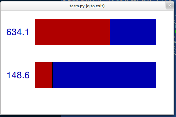
The relevant change is to duplicate the filtered value calculation and the rectangle creation.
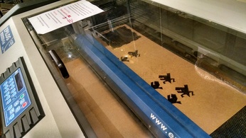
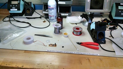
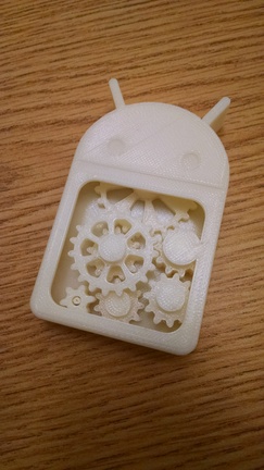
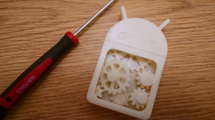
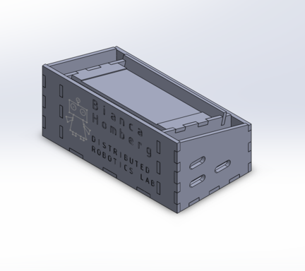
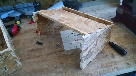
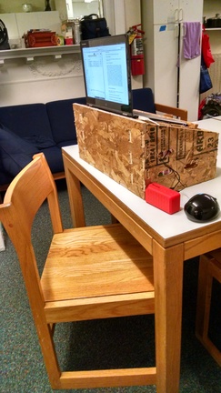
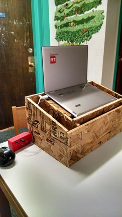
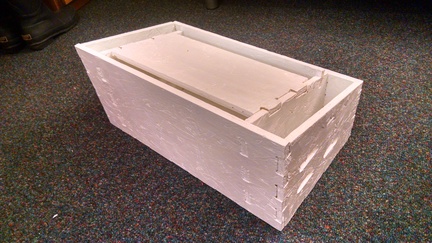
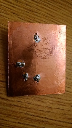
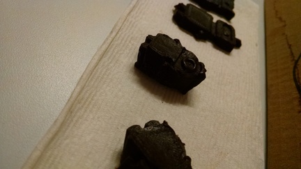
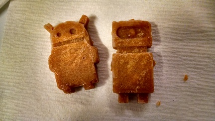
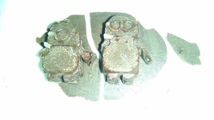
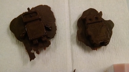
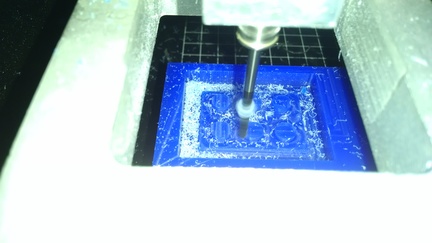
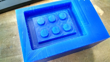
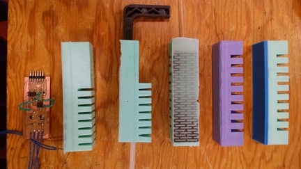
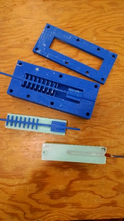
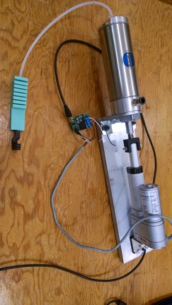
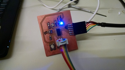
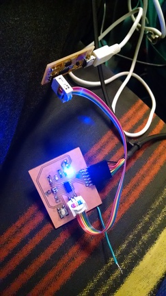
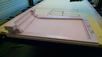
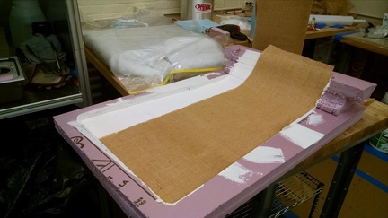
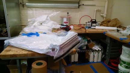
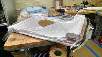
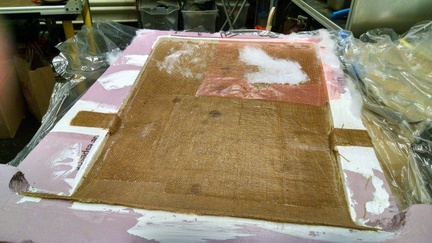
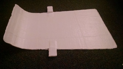
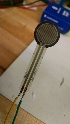
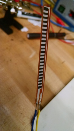
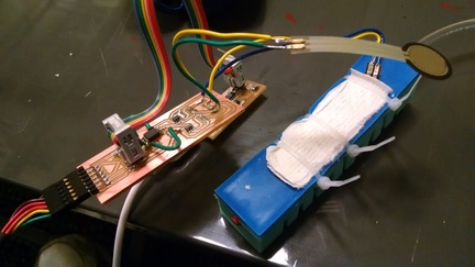
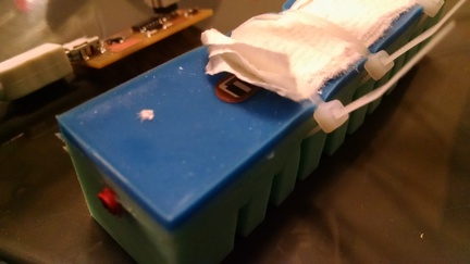
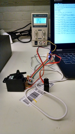
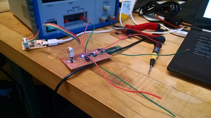
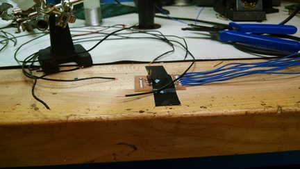
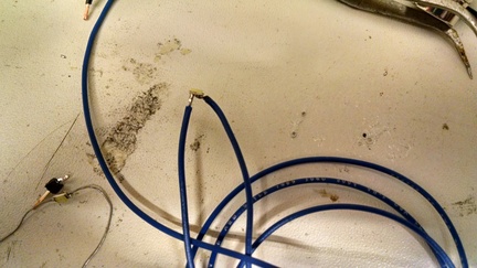
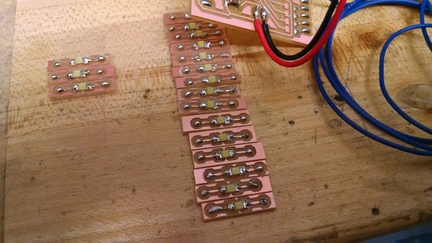
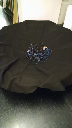
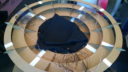
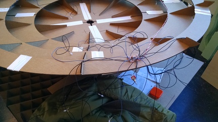
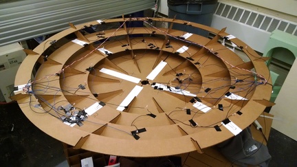
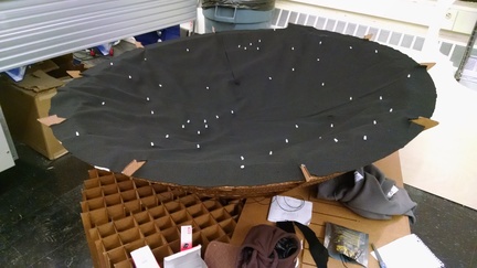
A picture of the sensor setup with the soft robotic finger:


A screenshot of the edited GUI:


ROS integration


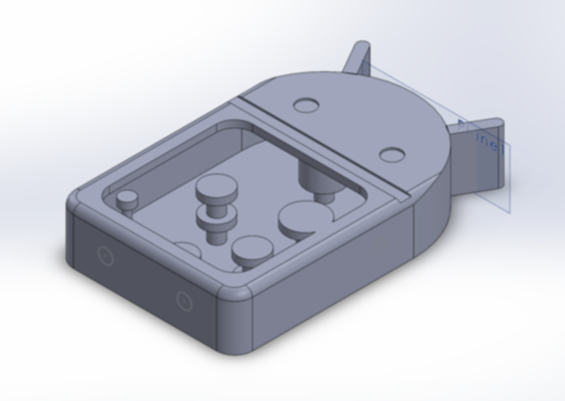
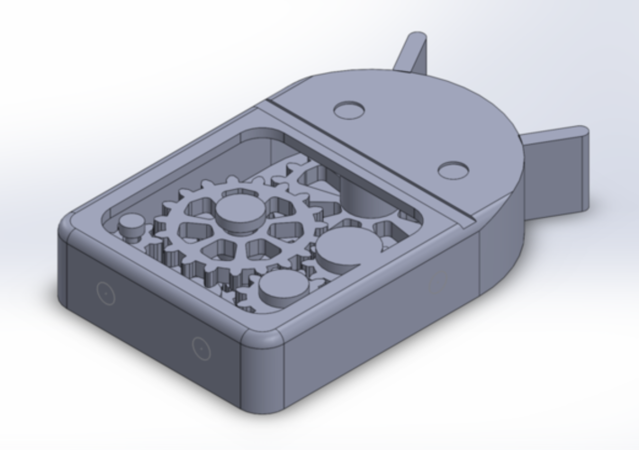
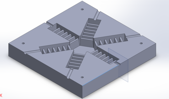
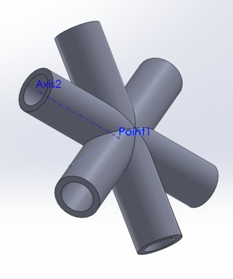
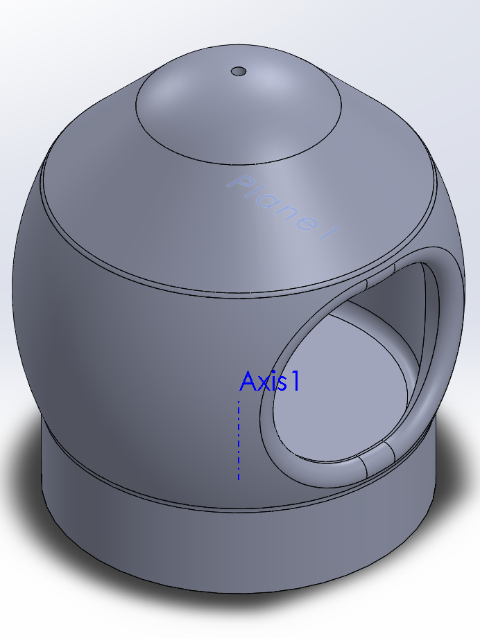
My goal with this input device is to get data back from the flex sensor to determine the curvature of a soft robotic finger. Towards this end, I have embedded the flex sensor in a prototype gripper. The next step is to create a ROS* node which will run on my computer to read in the serial input through the FTDI cable and publish the data as a custom ROS message. There are two options here: rosserial would run a rosserial_client node directly on the Arduino, communicating with a rosserial_server on the computer. This seems overkill, however. My current plan is to user a serial class to interface with the Arduino, read in the serial data, and then simply publish ROS messages independently.

I got this working using rospy and the Python serial class. (I ran into issues with the C++ serial class I downloaded -- it didn't seem to be reading the data correctly, and I kept getting strange values instead of the numbers I was expecting. Python made it a lot easier to deal with strings/ints/etc). I created a publisher node based on the code that read in data that Neil provided. Then, I published the sensor value in a custom message type to a new topic. And out came the data! Here is the code:


#!/usr/bin/env python
# license removed for brevity
import rospy
from std_msgs.msg import String
from test_code.msg import SerialMsg
import serial

eps1 = 0.5 # filter time constant
filter1 = 0.0 # filtered value

def go_publish():
    ser = serial.Serial('/dev/ttyUSB0', 9600)
    ser.setDTR()
    pub = rospy.Publisher('flex_sensor_vals', SerialMsg)
    rospy.init_node('serial_publisher_py', anonymous=True)
    r = rospy.Rate(10) # 10hz
    while not rospy.is_shutdown():
        global filter1, eps1
        global filter2, eps2
        #
        # idle routine
        #
        byte2 = 0
        byte3 = 0
        byte4 = 0
        ser.flush()
        while 1:
            #
            # find framing 
            #
            byte1 = byte2
            byte2 = byte3
            byte3 = byte4
            byte4 = ord(ser.read())
            if ((byte1 == 1) & (byte2 == 2) & (byte3 == 3) & (byte4 == 4)):
                break
        low = ord(ser.read())
        high = ord(ser.read())
        value1 = 256*high + low
        
        filter1 = (1-eps1)*filter1 + eps1*value1

        msg = SerialMsg()
        msg.type = 1
        msg.value = filter1


        rospy.loginfo("got filter value!")
        pub.publish(msg)
        r.sleep()

if __name__ == '__main__':
    try:
        go_publish()
    except rospy.ROSInterruptException: pass


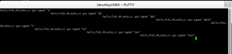
A screenshot of a rostopic echo of the data:


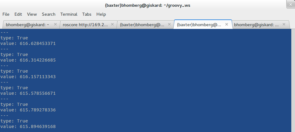
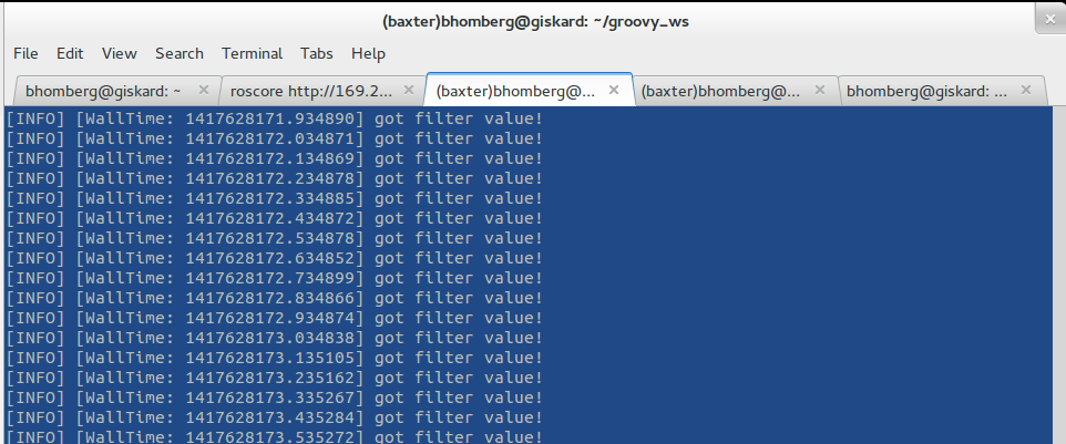
A screenshot of the debugging output:


* What is ROS? See www.ros.org. ROS stands for the Robotic Operating System, an open source, modular tool for programming robots. It runs as a series of distinct nodes which pass messages between themselves. So long as the master node is running, any other node can be instantiated to send and receive messages and control a robot system.

Week 13: Machine Building

West section made a painting machine!


I conributed to this week's project by milling and soldering the Fabnet board. (For our section, the TA forgot to bring some of the components, so I only partially soldered the board and we wound up using the TA's board.) I also soldered the power connection for the system and built the attachment mechanism for the end effector to hold the paintbrush in the machine. I also acquired the paint and the paintbrushes from my dorm for our use with the machine.

The full documentation for this project is on our class project page.

Week 14: Final Project

A large cardboard spaceship with LED constellations.

Pre-work: design

<<<<<<< local Solidworks design 123D make challenges w/ 123D make figuring out how to fit all of the pieces on to the 24 inch by 36 inch part design different components and attach them together. ======= I designed the shape of the rocket in Solidworks; the resulting model is below.


The largest challenge with this project was taking the large shape and creating slices in such a way that the resulting pieces will fit on 24x36 sheets of cardboard, since that's the largest size our lasercutter will hold. I wound up needing to split the resulting Solidworks design (using the mold Split command) into 11 pieces! While 123DMake will take as input the size of the material, it just gives you errors if it doesn't fit -- it won't optimize its layout to make the pieces fit. I got around this problem by cutting the larger spaceship into the separate pieces, each of which had no parts which were too big. 123DMake also wasn't the best at sorting pieces efficiently, but it was simple to take the resulting exported DXF files and rearrange them in CorelDraw.

The separate pieces I used fit into 3 categories: base, walls, and cone. The base was in 5 pieces: a center circle with four quadrants around it. The walls I was also going to split into corresponding quadrants, but the pieces were slightly too large to fit, so I will be going with 5 wall sections. The nose cone I made as one piece, but manually had to cut some of the DXF's into more pieces in CorelDraw.

Currently, the base and the nose cone has been lasercut; the cardboard for the walls didn't arrive until 6pm yesterday, so I didn't have time to do the full day of lasercutting they would have required. I'll finish the walls over IAP!

>>>>>>> other

Laser cutting

<<<<<<< local ======= I started by lasercutting the base, since it was the most straightforward. Figuring out the exact size to make the gaps for pressfitting was tricky; using small test pieces wasn't too effective since with larger number of intersections, it got a lot harder to press in, and small differences had a huge effect. The first piece I made, the center piece, was too loose, but the outside pieces had just a barely different gap size and they were very tight. Below, we see the inside piece and the first quadrant.


I used the same width gap to make the cone -- that was a mistake. While it wasn't overly difficult to put the quadrants together, since there was a good amount of leverage given the orientaiton, putting together the cone was significantly more difficult. For the radial pieces, I wound up squishing them a bit and sanding their gaps a little wider in order to manage the assembly.


The finished cardboard cone!


Here we see the full base with the cone upside down on top. All we're missing is the walls!


A lot of cardboar died in the making of this project -- and every single sheet had to be cut by hand to 24x36inches to fit in the laser cutter. I started getting a lot of papercuts and dry hands from pushing the cardboard together so much; I wound up wearing biking gloves which helped make it a lot better.


>>>>>>> other <<<<<<< local Lots of cardboard challenges...fitting shapes properly into 24 inches by 36 inches for the laser cutter...cardboard acquisition issues...had to hand-cut each piece of cardboard to fit into the lasercutter. Mini assembly line of one person. Figuring out right size for pressfit -- hard to gauge what it should be for so many pieces. Cone was especially hard to put together; had to sand the notches and squish the remainder of the cardboard. Wear gloves to avoid papercuts. Current strategy: binder clips to attach different pieces together. ======= >>>>>>> other

Electronics

<<<<<<< local 3 sections: high brightness LEDs, put inside there to make it bright, for reading. ======= I designed these boards to control LEDs that make up the stars of the constellations using EAGLE. Originally, I had planned to have only one board and drive 8-10 LEDs off of each pin, but I found that due to voltage requirements of the LEDs, I could at most drive 2 LEDs off of each pin. So I made three copies of the board, each running the same code. The board powers all 8 sets of LEDs, randomly blinking them on and off to make the stars twinkle. >>>>>>> other <<<<<<< local Also: microcontroller attiny44 with lots of LEDs attached, randomly flicker them on and off -- different brightness stars. Also make them twinkle. =======


>>>>>>> other <<<<<<< local Troubles: hard to solder wires to surface mount LEDs; need to have them distributed around cone to make constellations. Solution: acquired some through-hole LEDs, and made little mini PCB attachments for the surface mount ones. ======= There was a lot of wire cutting, stripping, and soldering! Since I needed lots of wire to make sure I could position the LEDs over the whole of the nose cone, I had to use really long wires.


My original plan was to solder surface-mount LEDs to wire. That turned out to be very difficult.


So as a backup plan, I milled a bunch of these: the world's smallest board, they had room for one surface mount LED and connection points for incoming wires. That worked, but was a lot of work. Luckily, a friend in the class had some extra through-hole LEDs, so I used those instead!


A second piece of electronics I worked on was to make 3 sections of high brightness LEDs. I want to be able to read from inside of the spaceship. I don't need any microcontrollers on these, just an on/off switch. I built 3 of these, but I'll probably place them at the top of the walls, so they haven't been attached to the nosecone. They're very bright, and making another one or two of these simple boards wouldn't be too much work if I need more light.


Assembly

The following series of pictures shows the assembly process. I started with black felt and cut it approximately to shape, then more exactly to shape by snipping cuts in it to make it better fit the curvature. I laid out and glued down (using hot glue) the three boards (all with connected power/ground).


Then, I separated each of the wires and organized them, planning how I would lay out my constellations.


After a lot of rearranging and bending over, I finally had all of the LEDs taped into place. (I started with hot glue, but it didn't dry very fast, so it would have taken too long).


I used these cutters to snip small holes in the fabric where the LEDs belonged then pushed the LEDs through. Here you can see the Little Dipper and some randomly assorted stars!


After putting in all of the LEDs, I cut the fabric exactly to size and glued the edges down. The constellations we have are the Little Dipper, Big Dipper, and Cassiopeia!


>>>>>>> other

Finishing Touches

<<<<<<< local Binder clips to attach pieces of the structure together Fabric for inside the cone/walls Eventually will cover pillows and put them inside. ======= Once I finish lasercutting the walls, there are a few finishing touches. I plan to coat the inside walls with the black felt as well to make a dark, cozy interior. I also plan to laser-cut fins to put on the outside of the base. I will lasercut a top layer for each of the sitting pieces for strength and cover all of them with pillows for comfort. I intend to hold the entire structure together with either binder clips or magnets or both.

>>>>>>> other

Supplies

<<<<<<< local Cardboard PCB material LEDs Wire Attiny43 Resistor/capacitor Felt Binder clips Hot glue ======= Cardboard - about $41 per box; the final project will use about 5 boxes with the walls (currently at almost 3 boxes for the rest of the spaceship). Definitely the most expensive part of this project.
PCB material - $0.70/large board - I fit all of my boards on one of them.
LEDs - cheap, used lots of them, <$5 total
Wire - I bought a 90ft roll of stranded wire for $9 since lab didn't have any left, also used some other spare wire.
Switches - I found them somewhere, free
Attiny44 - $3/each, $9 total
Resistors/capacitors - cheap, <$1 total
Felt - 5 yards at $3/yard for $18 total.
Binder clips - I bought 36 binder clips for $10. I may need more, not sure.
Hot glue - didn't use very much, <$3 >>>>>>> other