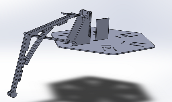
I'm going to need some springy legs. I brought my sketches from my final project proposal to life in SOLIDWORKS.
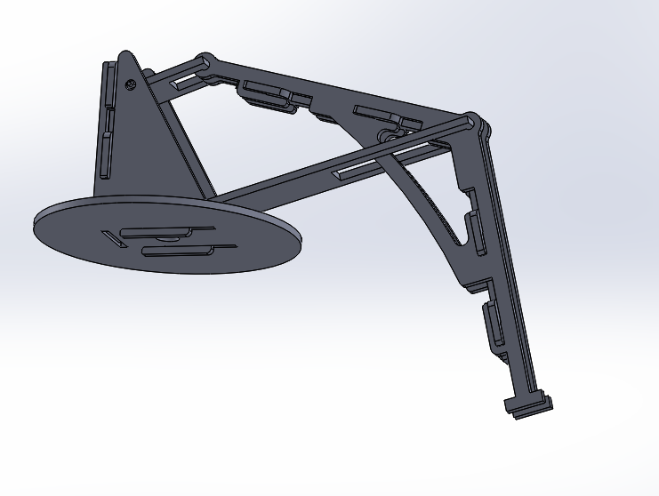
Here's the final assembly. It behaved wonderfully in reverse-kinematic simulation, as I dragged the parts around and confirmed the straight-line motion of the foot.
It can be a challenge to get the geometry of a linkage perfect despite the cloud of other tiny geometric features which need to end up in a realistic part: fillets, joints, holes, tabs and extra supporting material. I recommend sketching the global geometry first (an even cleverer way to do that is to use a master sketch, but I just sketched each one individually.
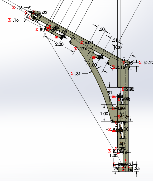
Here's the most complicated part of the leg. You can see the reference geometry on which everything else is based (dotted lines). I used centerlines, which are not treated as real geometry when extruding, revolving, etc.
I made extensive use of the techniques we learned for the press-fit project. Nearly all of the dimensions are parametric (red capital sigmas everywhere), linked to an external text file specifying global variables such as material thickness and the unit dimension of the linkage.
There wasn't much I could really know in advance about how big the leg should be, what thickness will be available for the material I finally make it out of, how large the tabs will need to be to assure rigidity, etc. So I tried to avoid the use of fasteners entirely, so that I could iterate extremely quickly on the leg design.
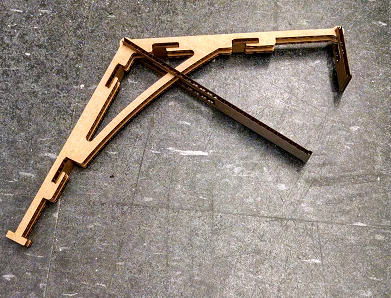
Laser cut a leg... Too big!
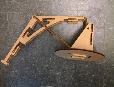
Laser cut another leg... That's better!
I hope to excite the robot at its resonant frequency, using a single actuator whose influence is spread out over all of the springy legs.
I knew I would need a circuit board with a DC motor controller, an accelerometer to track the movement of the body, a sensor to track the actuator, and a serial link for debugging.
The first board I designed had all of the above components except the sensor for the actuator. Full physiology:
- Power in
- ISP header
- Noise-absorbing capacitors
- Regulator
- Attiny44 microcontroller
- 2-axis accelerometer
- H-bridge
- FTDI header
It was a challenge to route it. It took about 3 hours of work, but I avoided using any 0-ohm resistors to bridge gaps. It's a pride thing.
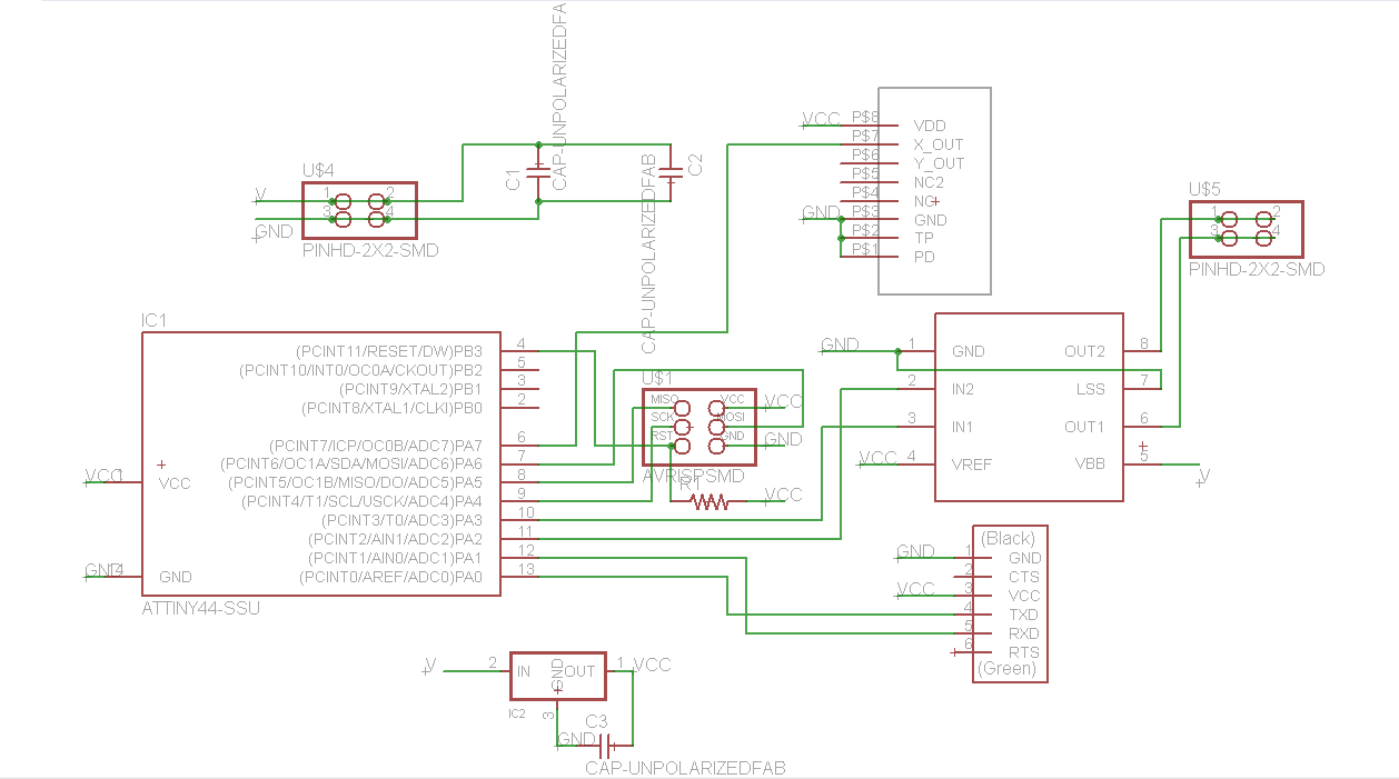
Eagle schematic
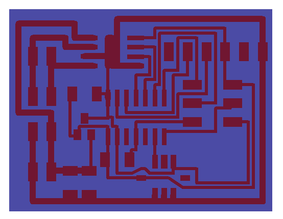
Eagle routed board
I should have left more space between the traces. It's an error which is very hard to correct at a later time in Eagle, and really, no one needs an absolutely minimally sized board! Make it a little bigger than you need; you'll thank yourself later.
As it was, I ended up with some absurdly small traces.
As usual, the board was stuffed in size order, smallest first, and secondarily from center to edges.
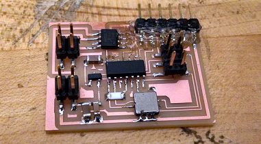
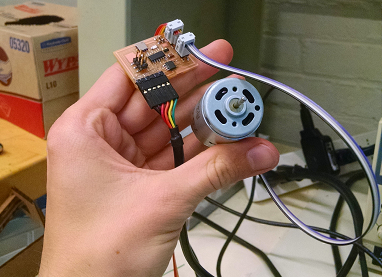
First project controller prototype.
Next I started a regime of tests to ensure that all of my electrical connections were correctly designed and manufactured.
I adapted the Hello Worlds for serial echo, accelerometer reading, servo control and H-bridge motor control in turn to suit my design. Mostly this process entailed superficial edits to the first few blocks of lines at the tops of the C and makefiles. One (the accelerometer hello) was written for the Attiny45, so I needed to change 45 to 44 throughout its makefile.
To my dismay, I found out that the hardware PWM is only available on the Attiny44's PA7! The aim was to use the hardware PWM to free up the processor to handle serial communications, control calculations and sensor reads. I didn't design my board correctly. Read the datasheet!
It's alright, though. I just rewrote my C code to share time between software PWM and the other functions. Luckily, there weren't too many balls to juggle.
The result is a functional combined motor controller and accelerometer reader.
Controlling a motor.
I modified the python script provided with the accelerometer Hello World to show just the axis of interest. It listens on USB serial for framing and data sequences from the FTDI cable.
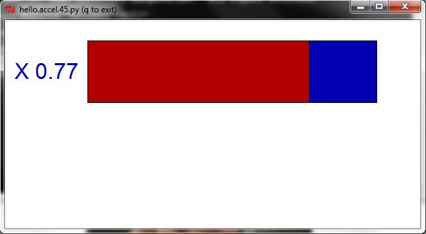
The python script showing a live update from the accelerometer.
Meanwhile, the SOLIDWORKS design continues to evolve...
Now it's clear where all those legs will go.
More soon!