I ended up sticking with my initial project idea for the final, with a few modifications. For a reminder, that project idea can be seen here.
The modifications I made were that instead of an LCD screen, there are LED lights. When the force on each pedal is approximately even, a red and blue light go on. When the left pedal is stronger, the red light goes on. When the right pedal is stronger, the blue light goes on. I changed this because of the time constraint. The LCD screen actually seems very manageable to learn and set up now, but before completing this project, I realized that I should start with LEDs (spiral project management). However, I am updating my week ten page to reflect what I now know about LCD screen use.
I started this project by working on electronics. It's a bit ridiculous, but until this week I hadn't managed to get any of my other electronics working, so this is the part I was definitely the most concerned about. I started by making the pressure sensors. By taking two small pieces of copper board, soldering a wire onto each side, and then putting a piece of conductive foam between the two copper boards, you can make a pressure sensor. I first wanted to prove the concept, so I quickly used the large copper boards and a large piece of foam and used the two leads on the volt meter to see the resistance change. It was quite effective!
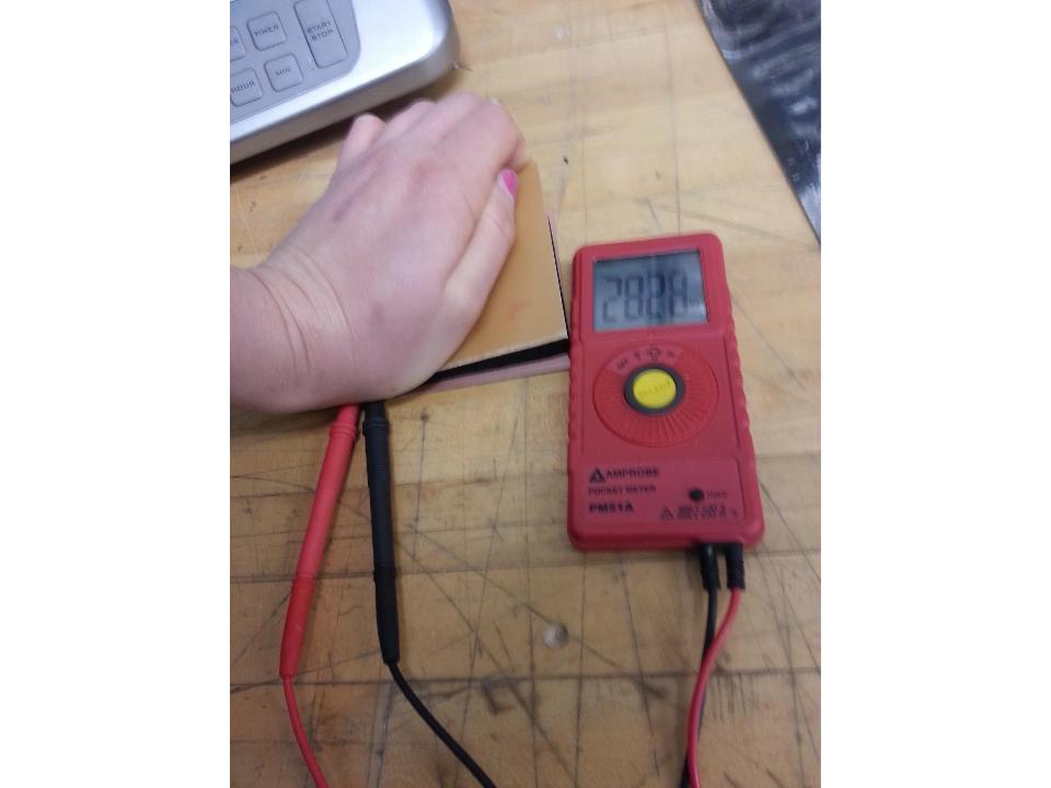
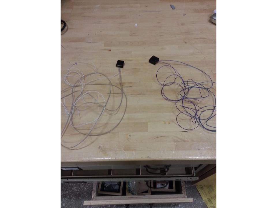
So, I decided to make the presure sensors that could be used in the project...
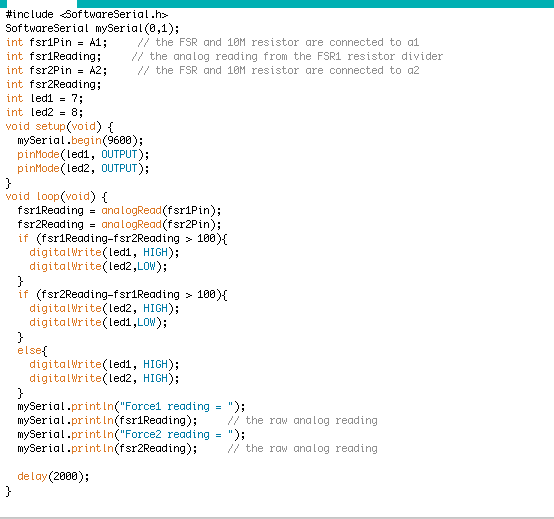
Next, I wanted to see it work with an arduino. So, I looked up the recommended circuitry for a force sensor and wrote a quick program to analog read the force data.
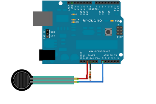
Despite following the circuit design, the serial monitor was only giving readings of 0. Once in awhile, I got it to change slightly. I thought the problem might be the resistor. I did a bit of reading and realized that the serial monitor spits out analog readings on a scale of 0 to 1023 based on the voltage passing through. As the total resistance changes, the voltage changes as well.

Originally, I was using a 10K resistor. However, if the conductive foam gives a lot of resistance, then the voltage passing through would be super low as well. I changed my resistor to 10M and all problems were solved. It was super exciting to get legitimate read-outs from the pressure sensor.
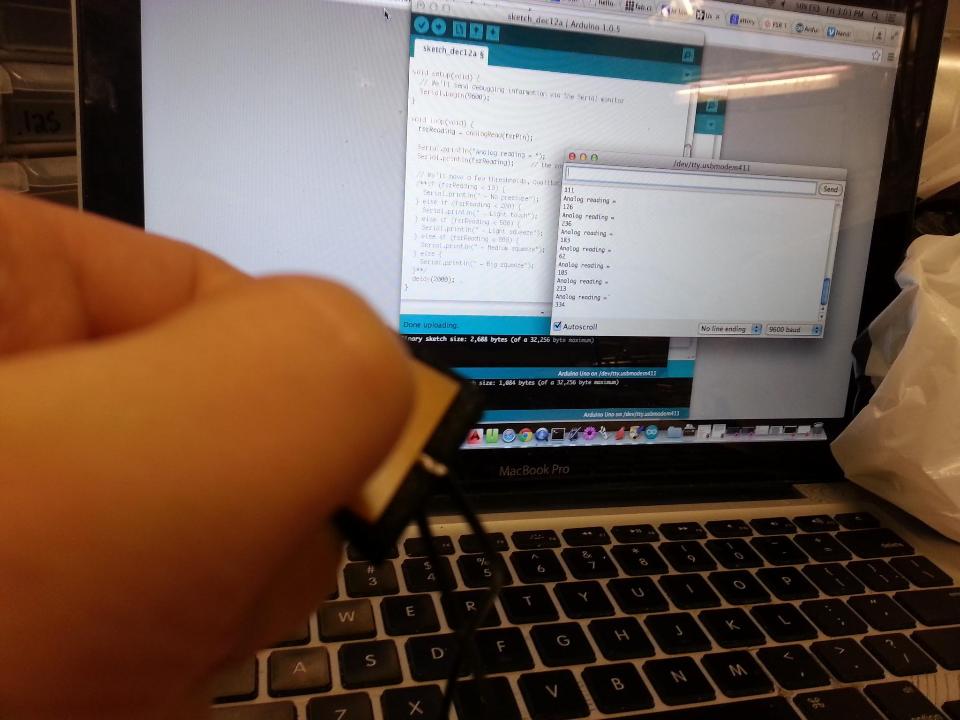
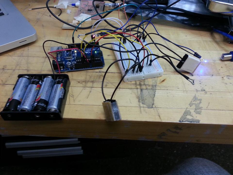
Next, I decided to try to make the entire circuit using an arduino. At least I would know my circuit works to help with problem isolation later on. Below is the entire test circuit.
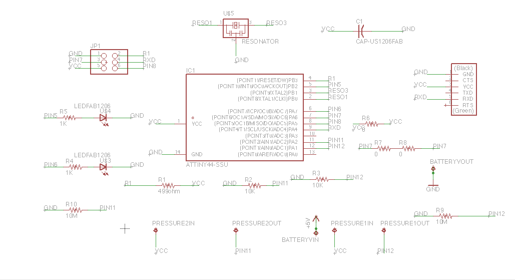
Once I proved that the project would work, it was time to try to make my own board. I designed the entire arduino circuit in Eagle. I had to add a resonator, a capacitor, a power source, and a programming method. The 2x3 header is the standard programming method. I decided to use an FTDI cable as a power source because I think it is also a way to read data from the circuit when it's plugged into the computer. I also designed some spaces for batteries because I want to be able to use this on my bicycle where I hopefully would not have a computer. I also finally was introduced to the ATTINY44 to arduino mapping.
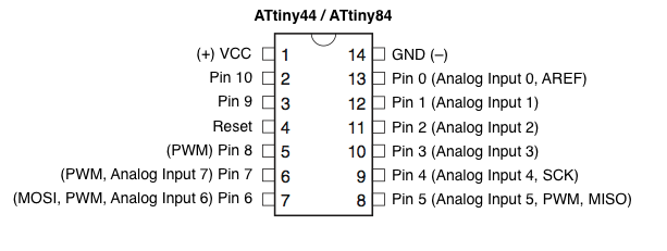
I realize that's something that I totally should have known before. I made sure that the pressure sensors were on ATTINY input pins and that the LEDs were on ATTINY output pins. Eventually, everything was accounted for on the circuit.
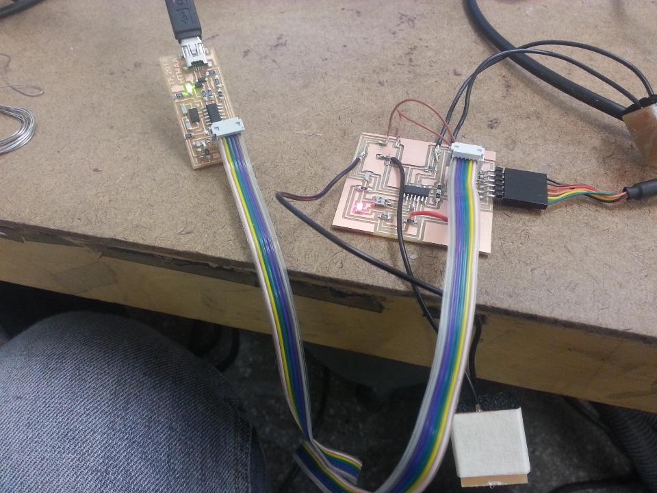
Then, I routed the board by hand. There was one wire I couldn't get to work, so I figured I'd just use a jumper cable later on.
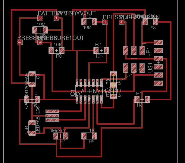
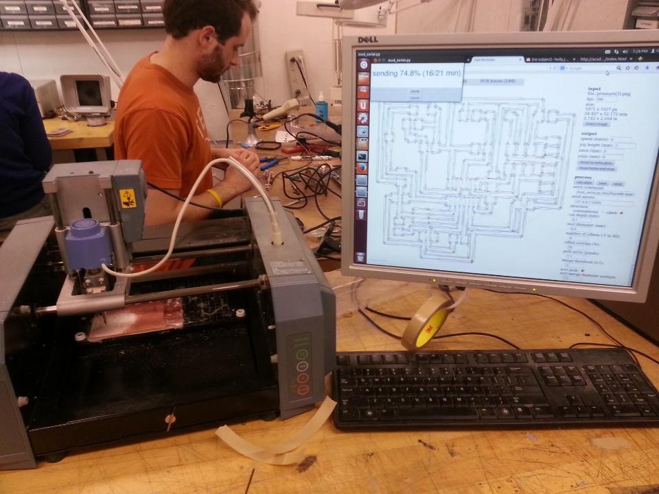
After that, it was time to mill.
I stuffed that board as carefully as possible. As mentioned before, I had not been successful with electronics this entire semester. It was partially because I was doing things incorrectly, but some of the time it was just because of dumb stuffing mistakes. A dumb stuffing mistake can lead to hours of tring to debug. So, I stuffed as carefully as possible. Once it was stuffed, I wanted to test it. I wrote a program just to turn the LEDs on.
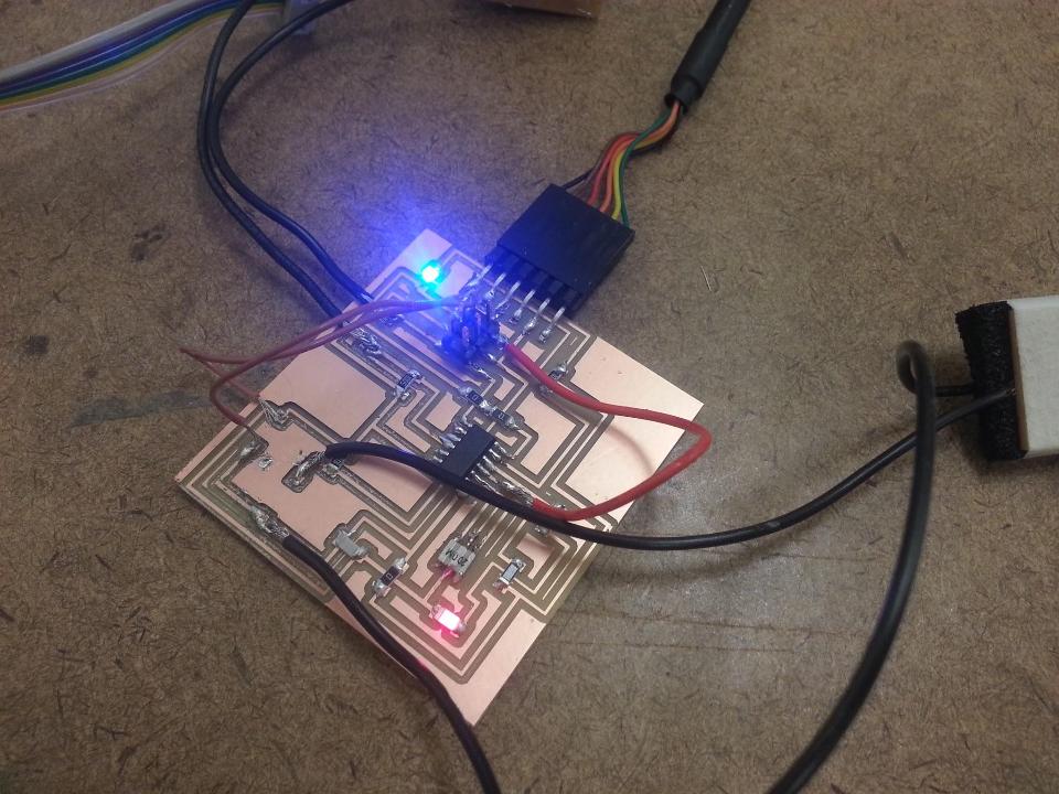
It worked! Next, it was time to try the program that was used on the arduino to have the LEDs respond to the pressure sensors. Here is the code I added:
Miraculously, that worked too! Here's a video of the lights responding to the pressures:
IMG 2685 from Holly Josephs on Vimeo.
I felt pretty good about the electronic component, so I figured I could move on to the setup on my bicycle. I wanted to make a press-fit display area so that the circuit board with the LEDS and the batter pack could sit on the handlebars. I also wanted to make pedal covers so that the pressure sensors could be attached easily. The display was designed in 2D and the pedal covers in 3D. I started with a few sketches:
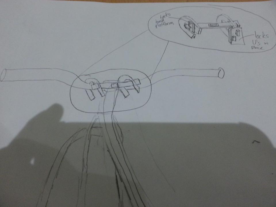
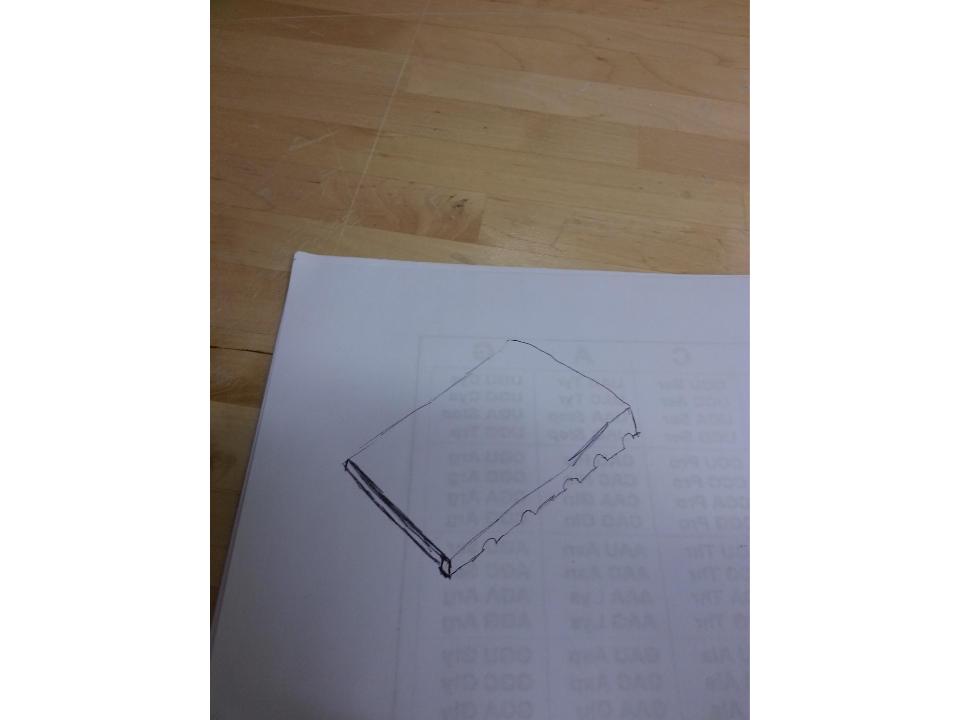
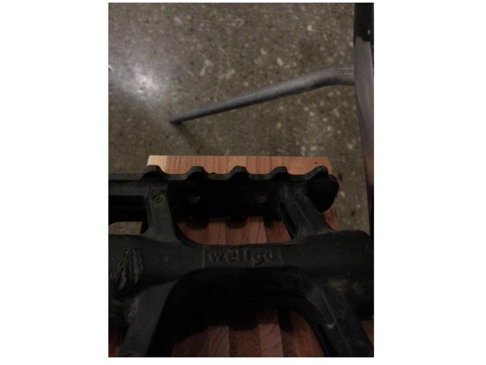
The pedal covers just had to match some grooves on my pedals. I measured the pedals to get the spacing correct. As for the display, I just thought a bit about press-fit locking mechanisms and how to get a flat area for the circuit board and batteries.
Then I went on to CAD them in Rhino.
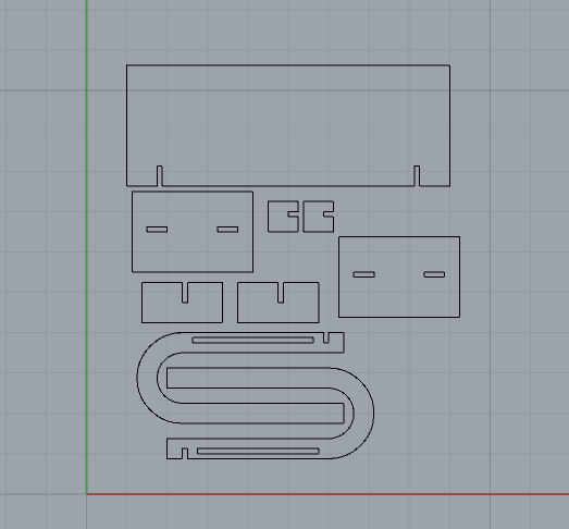
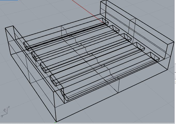
I then milled the pedals on the Shopbot.
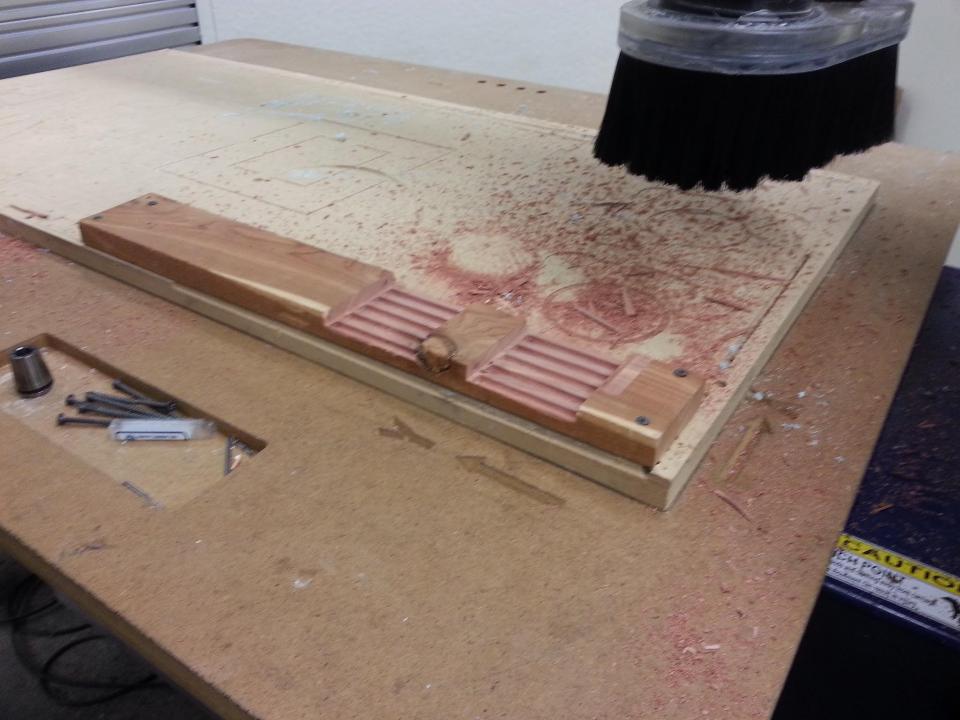
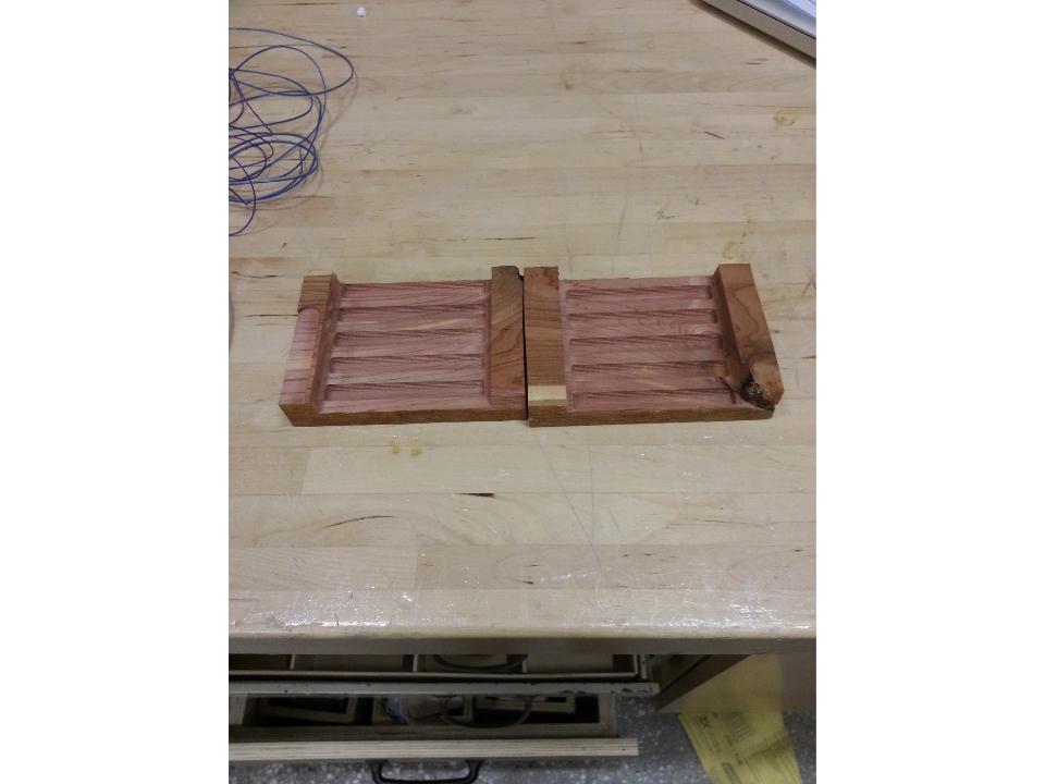
I was happy that the covers fit well. I used wood glue to attach them.
With the pressure sensors...
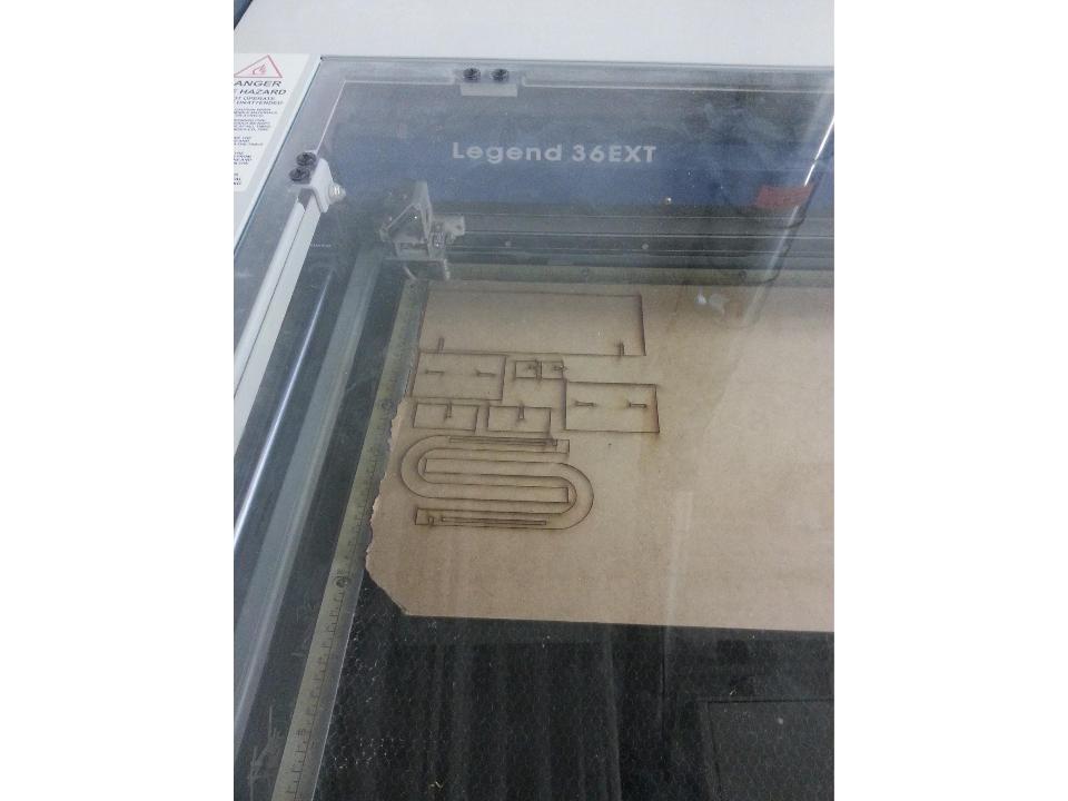
Next, I laser cut the display. I used 1/8 inch masonite and cut at 25% speed and 100% power.
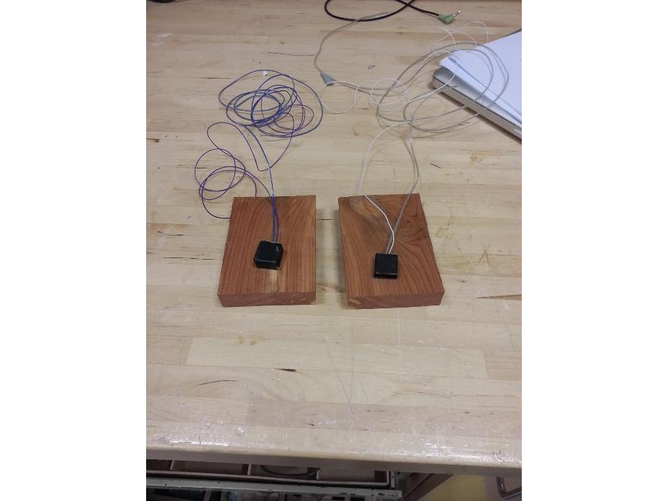
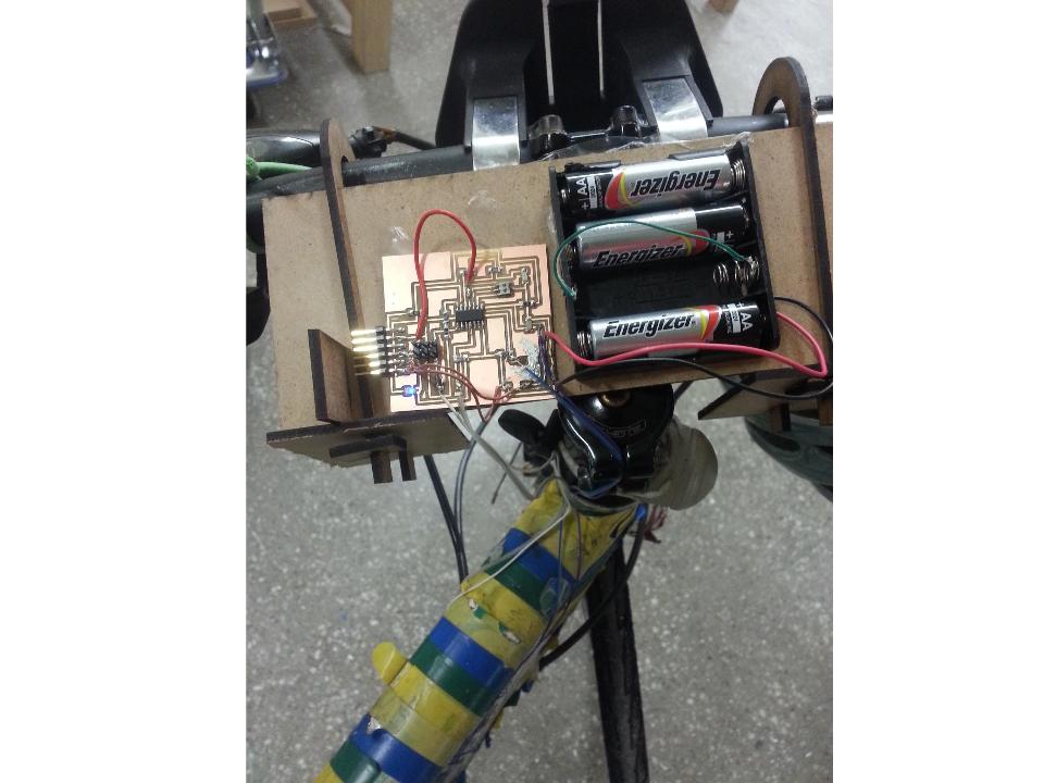
Finally, all of the pieces were ready. I assembled the display onto my handlebars and used double-sided tape to attach the board and batteries.
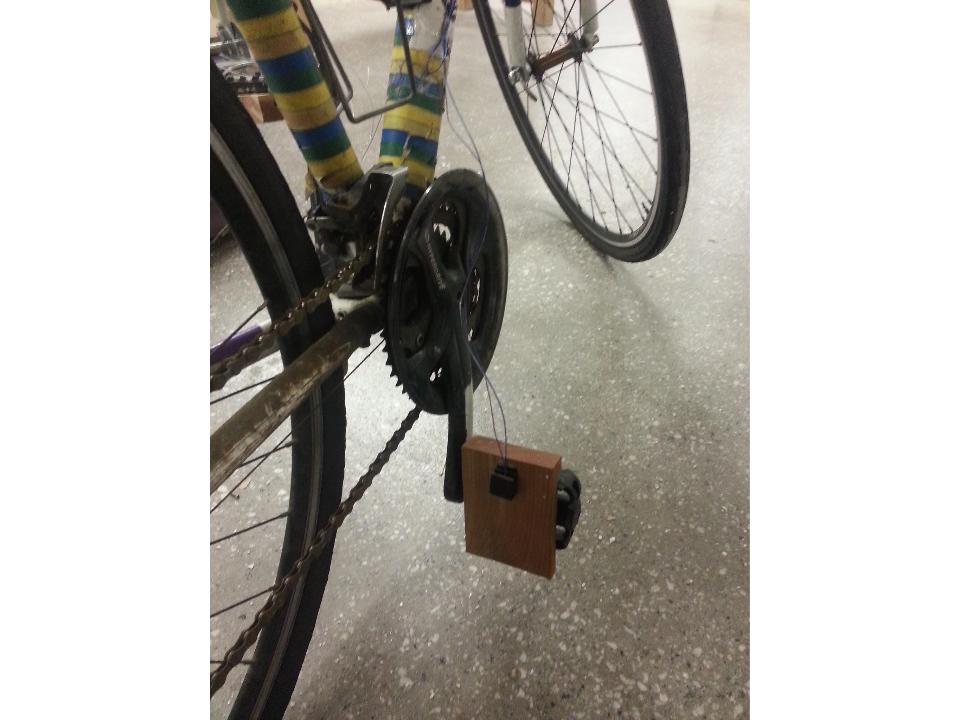
I attached the pressure sensors to the pedals and made sure there was enough loose wire to pedal. I taped the rest of the loose wire to my bicycle frame.
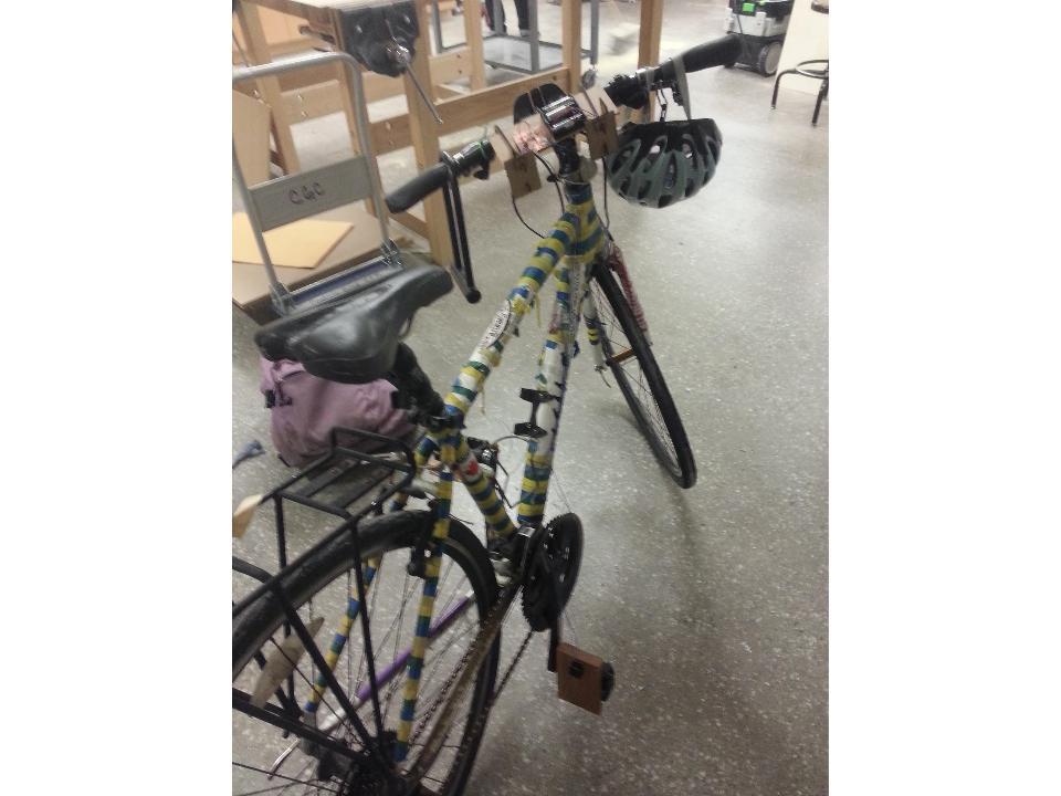
Here it is, all together :)
As for costs, I think this is super cheap. The ATTINY is about two dollars, the rest of the components probably add up to a dollar, the wood is probably worth a couple of dollars (but I found it in the scraps) and the batteries cost about 3 dollars. The project needs work to be more versatile, but, all in all, I learned a lot this week by doing it and it was pretty satisfying to finally get some electronics to work. I hope to make a compilation of super basic things I wish I had known all along that would have made electronics easier. Thanks for reading!