
Final Project
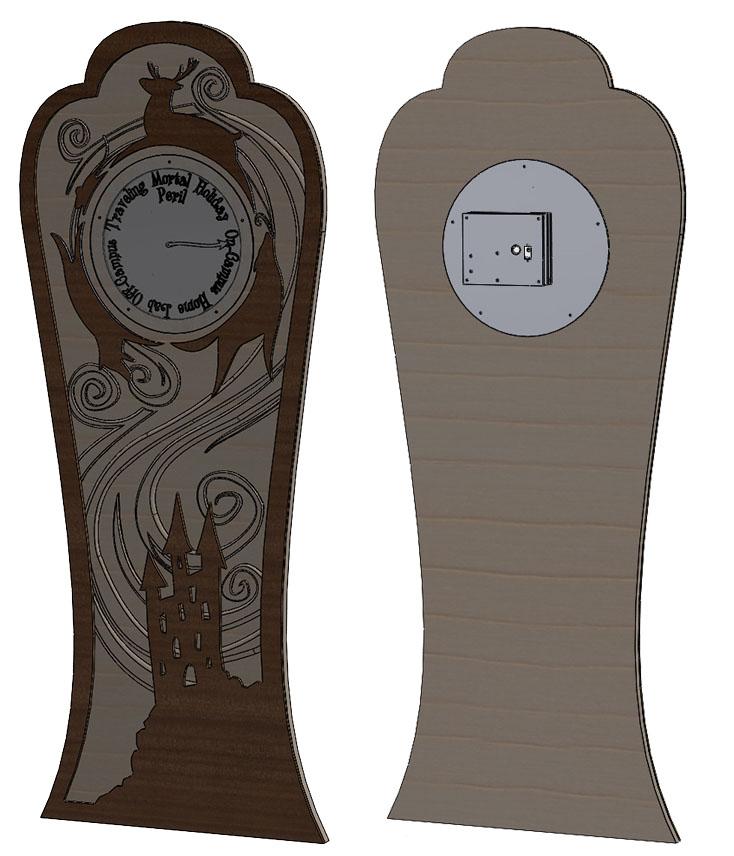
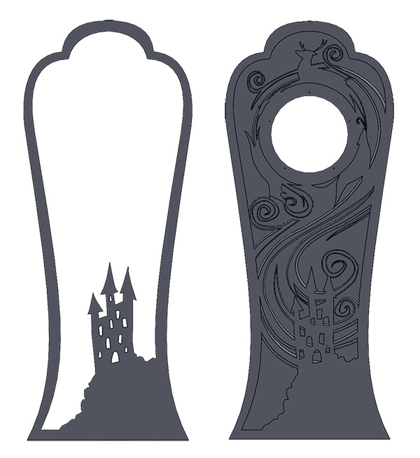
For the final project, I had my heart pretty set on my original proposal. Over the semester, I'd spent some time drawing a design I liked a lot more.

|
|
However, I realized that with the final project, I would have to scope things down a bit. I decided to treat this as sort of a first prototype, with the plan to build upon it over IAP.
The Clockwork
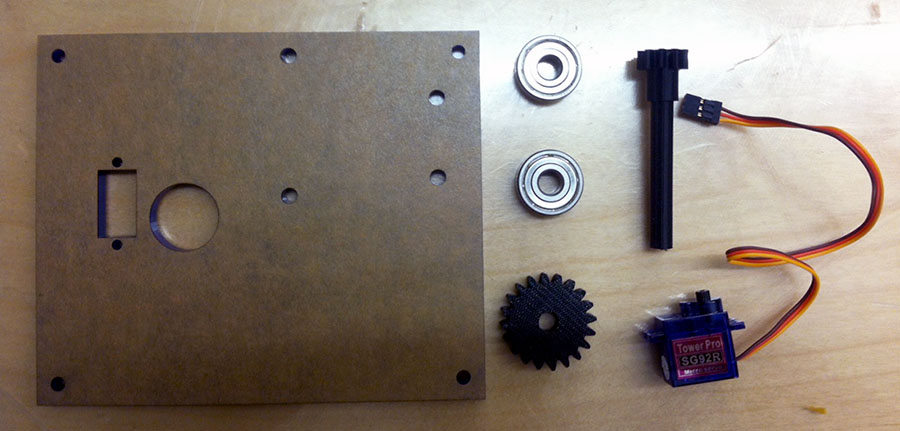
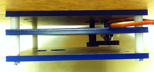
I wanted to run the clock hand with a servo, since it is an easy way to specify what angle the hand needs to point, and there were servos provided by the class. However, since most servos (included what was in the lab) go 180 degrees, I used a 2:1 gear train to make the hand go a full 360.
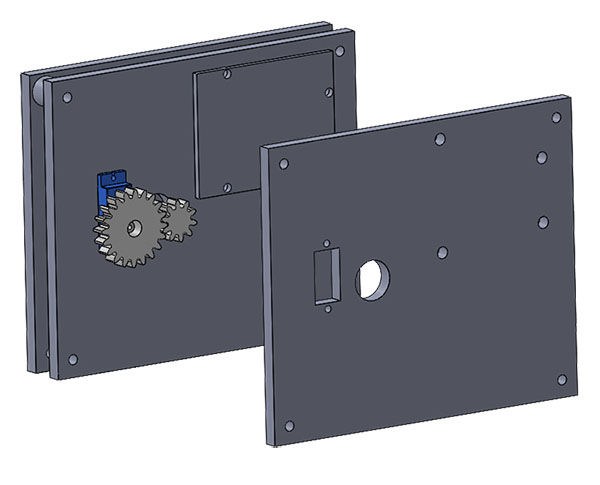
I decided to 3D print the gear and the axle for the clock hand in one piece. A plastic 3D printed axle isn't especially structural but since the only load it has to bear is the clock hand, 3D printing was good enough for my purposes. I printed it on the Dimension so it would be made of a more structural material. For the gear attached to the servo, I printed it such that I could take the existing plastic "arms" that come with the servo, cut off the arm, and press fit the remaining part into my gear. That way I had a gear that fit right onto the servo with no problems. I laser cut the flat plates of the assembly.
|
|
Here's a short video of the clockwork assembly in action.
Electronics and Software
My original goal was to send GPS coordinates from my phone to a webserver, pull that data with a WiFi enabled microcontroller, and use that to control the servo. However, I wasn't able to get quite that far! For the final project, I decided to simplify my plans and control the servo from my computer, using a basic user interface. However, to see what I tried before simplified, keep reading!
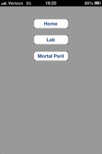
Fortunately for me, my friend Zach has a lot of experience in creating iPhone applications, so he helped me with this part of the project. We decided to start by manually sending the location to a webserver before trying to figure out GPS. To do that, we wrote a really simple iPhone app in XCode (you can see we only have some buttons for testing purposes).
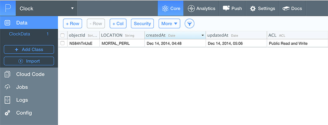
 Then, we used Parse as a way to send and store the data. Parse allows you to write data to a table stored on their webservers. You can see in screenshot below that it stores the location. We wrote it so that it updates the location rather than adding more rows to the table, but that would be possible as well.
From there, we wrote a really simple test website using HTML and Javascript. The URL is: http://web.mit.edu/jasminef/Public/Clocksite/index.html. You'll notice if you click on it, the URL will be appended by a location tag like #MORTAL_PERIL or #LAB. This is one way we were trying to pass information to the microcontroller (we also tried writing directly to website).
Unfortunately, what we didn't take into account was the fact that the microcontroller doesn't process javascript. So when we tested reading the data in using an Arduino and a WiFi shield, what we found was that the WiFi shield read the HTML code but didn't run the javascript. We tried using Johnny Five, but eventually I decided, in the interest of time, to just try to get something running from my computer and save trying to get it running on WiFi for later.
Running it from my computer was a much simpler project - I simply modified my code from Assignment 12. A demo of it is below, along with a clock face.

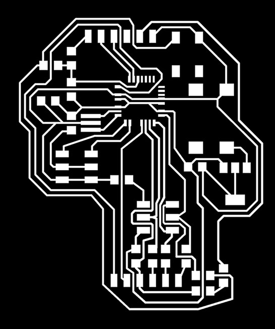
For the electronics, I used a fixed version of the Fabduino I designed from Assignment 10, where I added in the missing traces for CS. Since I wound up not using the WiFi shield, it turned out to be somewhat unnecessary to use a Fabduino in the end, especially since I designed it to run off an external power source.
The Clock Body
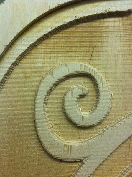
I made the clock body in two parts (not including the clock face). The first was a 1/4" piece of plywood that provided the top layer. The second was a 3/4" part for the bottom layer. I used the ShopBot to carve both pieces. The first piece was a 2D profiling cut so it didn't prove much difficulty.
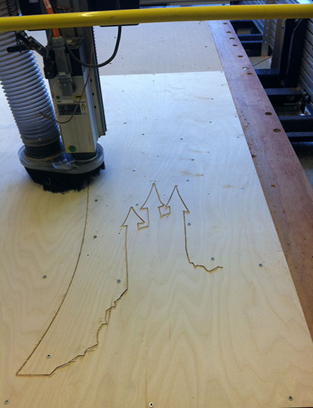
However, the second was a 3D toolpath (because of the filleted edges on the sweeping wind shapes). This proved a lot more difficult - the Shopbot 3D software we had access to only rasters, and so it wanted to pocket the piece in a way that didn't entirely make sense. Instead, I wound up pocketing the cut in the 2D software using a 1/4" end mill, and then using the 3D software for the finish cut with a 1/8" end mill. Even with the 1/8" end mill, the surface finish was pretty poor (and it took about 3 hours to complete). I could probably sand it or paint it to hide it, but after talking to Hayami at the Hobby Shop, I plan on remaking thing over IAP using different toolpaths and out of solid wood rather than plywood.
|
|
Other lessons I learned with the ShopBot:
- I didn't have access to a down cutter of the right size, so the plywood splintered pretty badly in some places.
- We weren't initially taught the formula for figuring out the feed rate to the RPM ratio. Here's the feed rate/RPM formula. For the IDC ShopBot, James recommended 16000 as a good RPM.
- Warm up the spindle before using the ShopBot if no one else has used the machine yet that day (on the IDC Bot, the option is under "Cuts").
- Use the prox switches (under "Zero") to find the absolute X,Y value of the machine. Then, jog to where ever you want, write down the coordinates, and set it as home. That way if something happens, you can always find the same X,Y zeros.
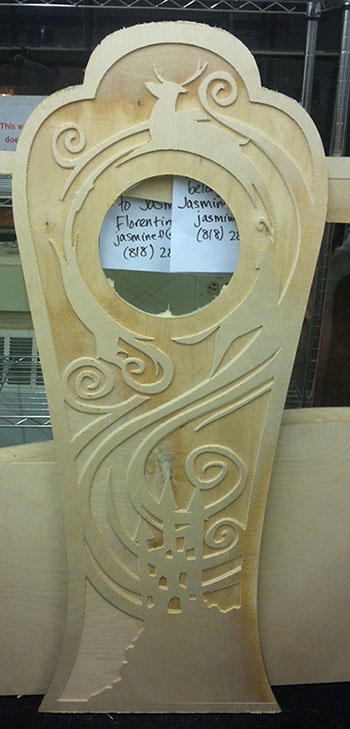
I did a bit of sanding to get rid of the splinters as best as I could, but I decided since I was so unhappy with the surface finish of the main body, to treat this project as sort of a "prototype" for re-doing this out of solid wood over IAP. Because of that, I decided not to invest a lot of time into trying to finish the surface.
When I went to assemble the whole thing, I found out that the 1/4" piece, which I'd cut several days before the other and left in another location, was actually sized differently! Apparently, when I opened the .dxf file, it must have resized the file. At this point it was a bit late to fix it, so the design came out slightly different than what I'd originally planned.
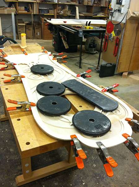
I assembled the wooden body with wood glue, and used clamps and weights to hold it together while it dried.
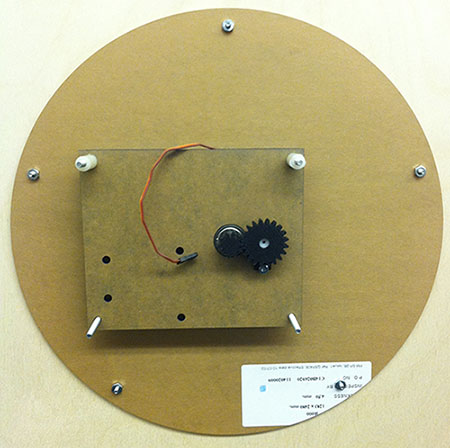
I made the clockface by lasercutting it out of acrylic (since that's what happened to be on hand), and spray painting it silver. In hindsight, I think the spray paint would have come out better if I'd sanded the surface of the acrylic first.
The Full Assembly
My last step was to put everything together! This mainly involved bolting everything, since I designed the clock to be something I could take apart again later, for when I improve on it over IAP.
Future Work
My future plans for the clock are:
- Getting the GPS on my phone to control the servo. Ideally, I can do this with the electronics I've already designed, but I'll also look into other options.
- Remaking the body out of nicer wood, and spending more time on sanding and finishing (maybe painting it)
- Water jetting the clock face out of metal. I may also add more to the design of the clockface so it isn't so bare.
- Possibly adding more clockhands for multiple people.
Thank you!
I was only able to get this far with my project thanks to the help of a lot of really awesome people. Thanks especially to Zachary Barryte, James Coleman, Jonathon Bobrow, Ken Stone and Hayami Arakawa for helping me with the final project!