Week 5: Electronics Design

LED Circuit Board
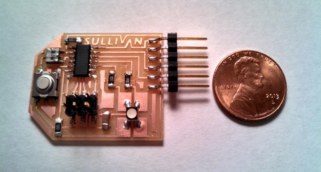
The objective for this week was to make a circuit board with at least one button and one LED. I chose to use an RGB LED allowing me to create a spectrum of colors.

Eagle Schematic

Eagle

This was my first time using Eagle and I wasn't very good at it so my design is very closely based on the circuit shown in class.

The picture on the right is my poorly labeled circuit schematic in Eagle. I didn't really bother with trying to make the schematic look nice since all I really cared about was the .png image at the end.

As you can see at the top of the picture I used an RGB LED which had four different pads (one for each color and a final one connected to the power supply). When I was trying to figure out how to add the LED to the circuit I looked at designs from the previous year and I got a lot of help from Rotem Abeles' page. From his page I was able to figure out which resistor and LED component to use in Eagle (I used LEDRGBNEW for the LED).
Eagle Board

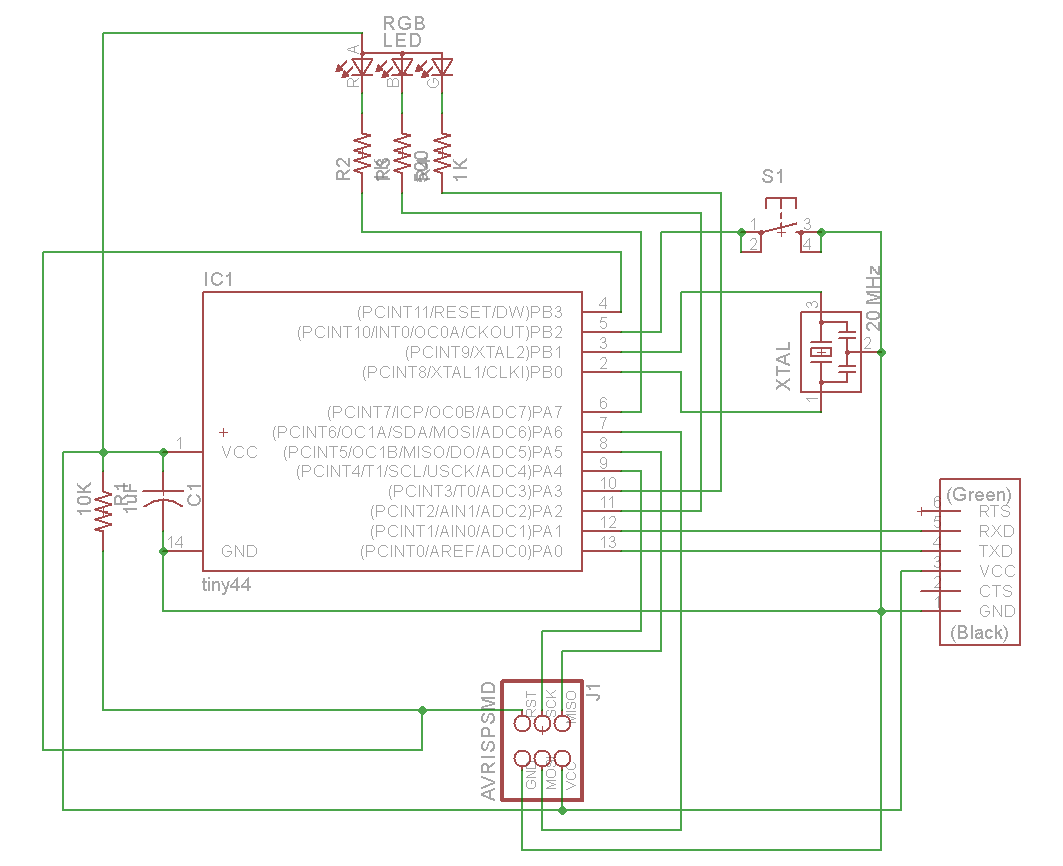
The picture on the left shows the corresponding Eagle board. I used a wire thickness of 0.012 inch which worked ok but they're very fragile. Also the length of the pads for the 20 MHz resonator seemed a bit too short. The pads were only slightly longer than the resonator making it very difficult to solder. Everything else seemed to work out great.

Editing the .png Files

Once I was done designing the board in Eagle I exported the traces and the exterior cutout as .png files. I wanted to add my logo to the board but have it actually carry current. I purposely left a small space at the top of the board, which you can see in the previous image, so that I could use my logo to replace two of the wires.

I then opened the .png file in Microsoft Paint and placed my logo in the image with enough spacing between the letters for the mill to pass through. After it was all done I had my traces and cutout .png's.

Milling and Soldering Milling

Milling went very smoothly. Everything worked on the first try, although like I said before the wire thickness was a little thin so some of them came out weird looking. Before Soldering

Soldering also went well but the resonator was pretty difficult to mount and I believe one of the attiny's pads came unglued when I was soldering it.

Mistakes I Made

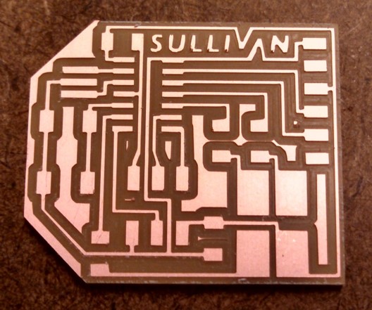
The biggest mistake I made was making the wires too small. I would suggest a minimum wire thickness of 0.016 inches. Also when I was designing my board I wanted to make it as compact as possible but in hindsight that made milling and soldering much more difficult.

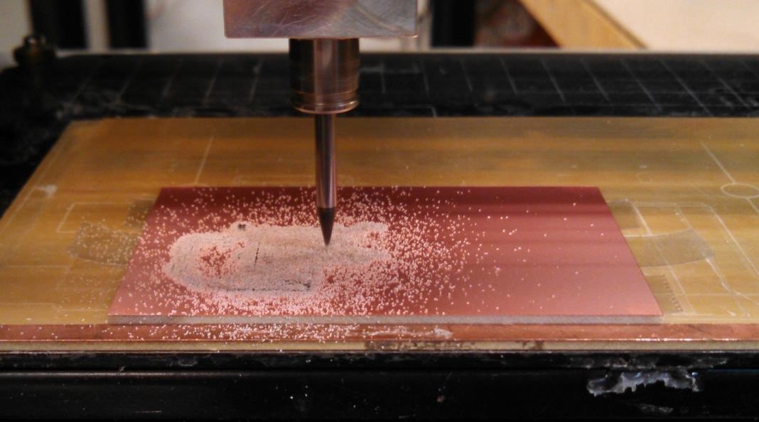
Another thing I noticed a little too late is that I think I may have used a dull 1/64th inch bit in the mill because I realized that it had cut really crooked lines especially when they were diagonal. I didn't notice this until after I had soldered the board and looked through the pictures I had taken.