Just about every 3D printing software I know of uses some kind of slicing algorithm to separate a 3D model into stacks of XY layer planes, and convert this information into code that the 3D printer can understand. I am relatively familiar with Ultimaker 3D printers, which directly accept the gcode formt. This was my first time using a Makerbot, which uses a binary format called .s3g or .x3g. I can't say I see any advantage to this other than just Makerbot just wanting to add another layer of encryption so their technology would be more difficult to tamper with.
After a good bit of trial and error, I found a way to convert gcode to .x3g using a program called ReplicatorG. Finally, the process I used was as follows:
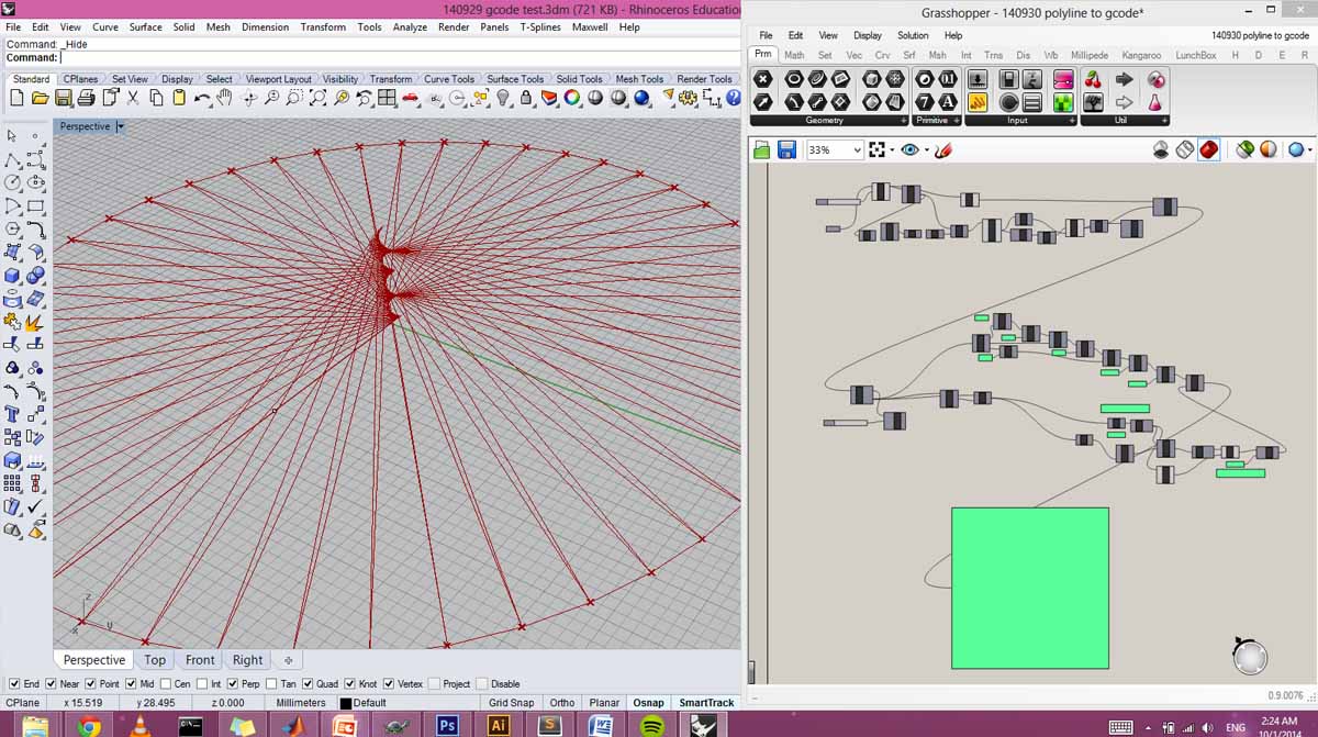
1. Create a line network or polyline to become the toolpath. I tended to use a single polyline as it didn't leave any curve sorting to chance.
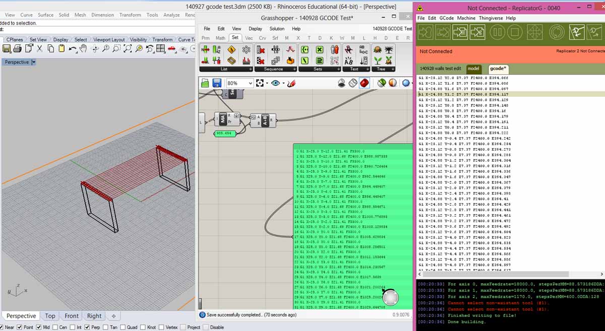
2. Input curves into the Grasshopper definition. Adjust settings for feed rate and extrusion length. Copy the text from the panel object to the clipboard.
3. In ReplicatorG, import an .stl file and prepare it with settings relatively similar to what you're looking for. Click "generate gcode". Then, under the "gcode" tab, delete all of the coordinate information in the body of the text, leaving only the "header" and "footer". This ensures that the settings are correct and compliant with the Replicator flavor of gcode. You should of course read over the settings and make sure they seem correct. Finally paste your copied text from Grasshopper between the header and footer.
4. Click on the icon to generate a .x3g file. This is the only find of file that Makerbots will accept. Save to SD and print.
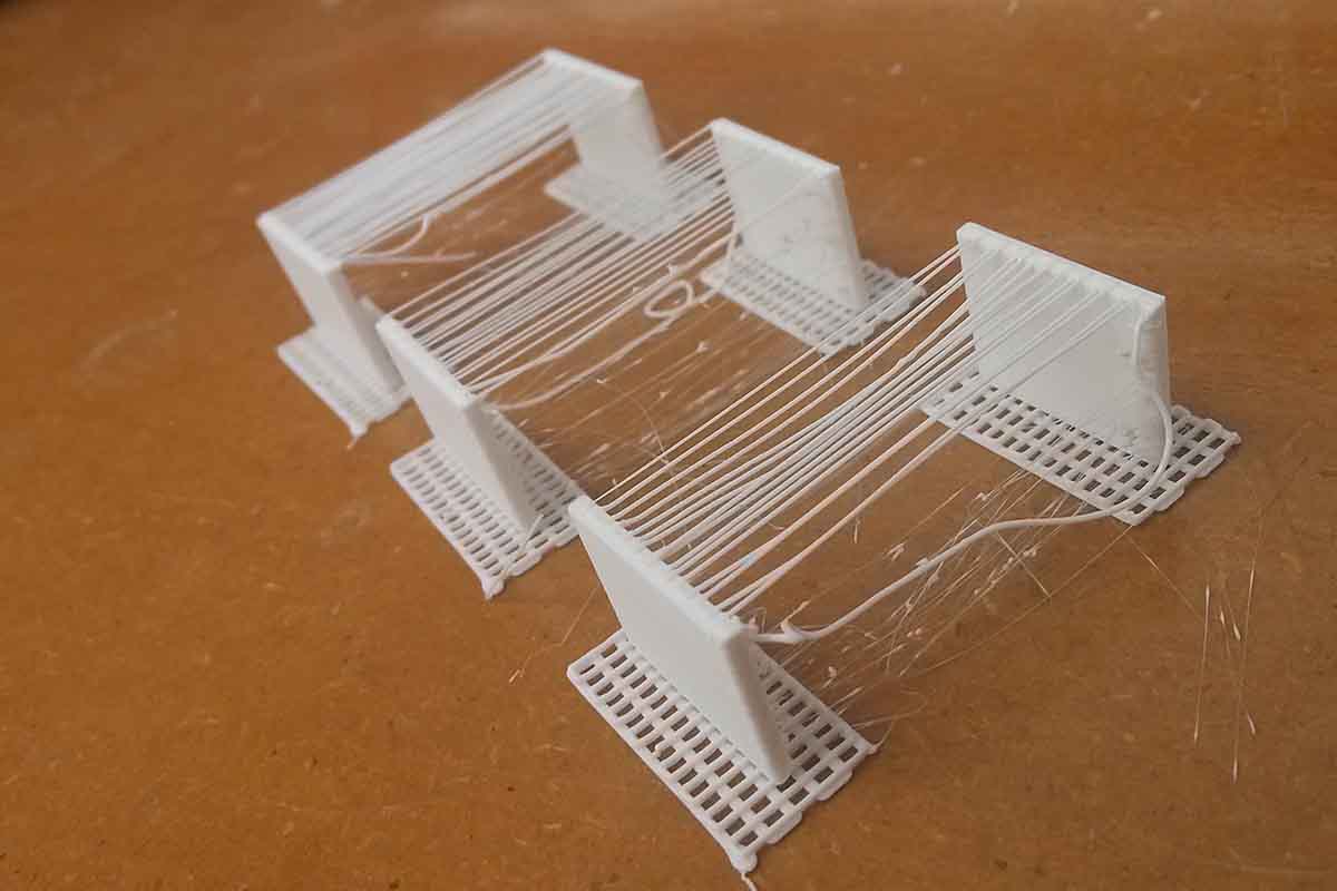
First I printed a series of tests incrementally adjusting the speed of motion and the amount of extrusion. Extrusion is represented by E in gcode, and is a cumulative value representing the length of filament used since the start of the print. I was hoping to create smooth catenary curves, but found this to be quite difficult due to irregularities in adhesion.
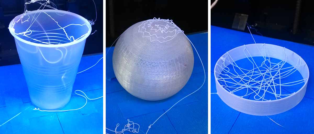
Further tests included printing overtop of other 3D objects. This was the beginning of moving the head in 3 dimensions. I realized that due to the mass of the extruder head, the distance the head could travel in the Z dimension was still quite limited. For example, it wouldn't be able to cover more than the top of the sphere before the head pushed the sphere away.
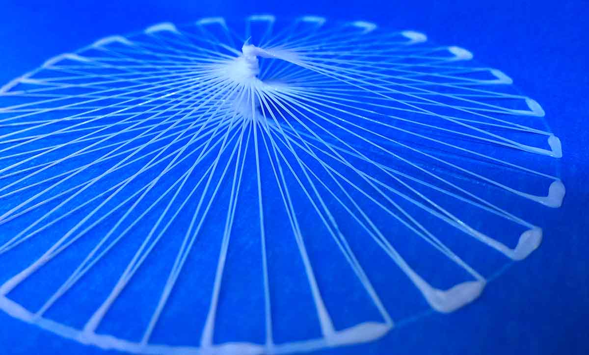
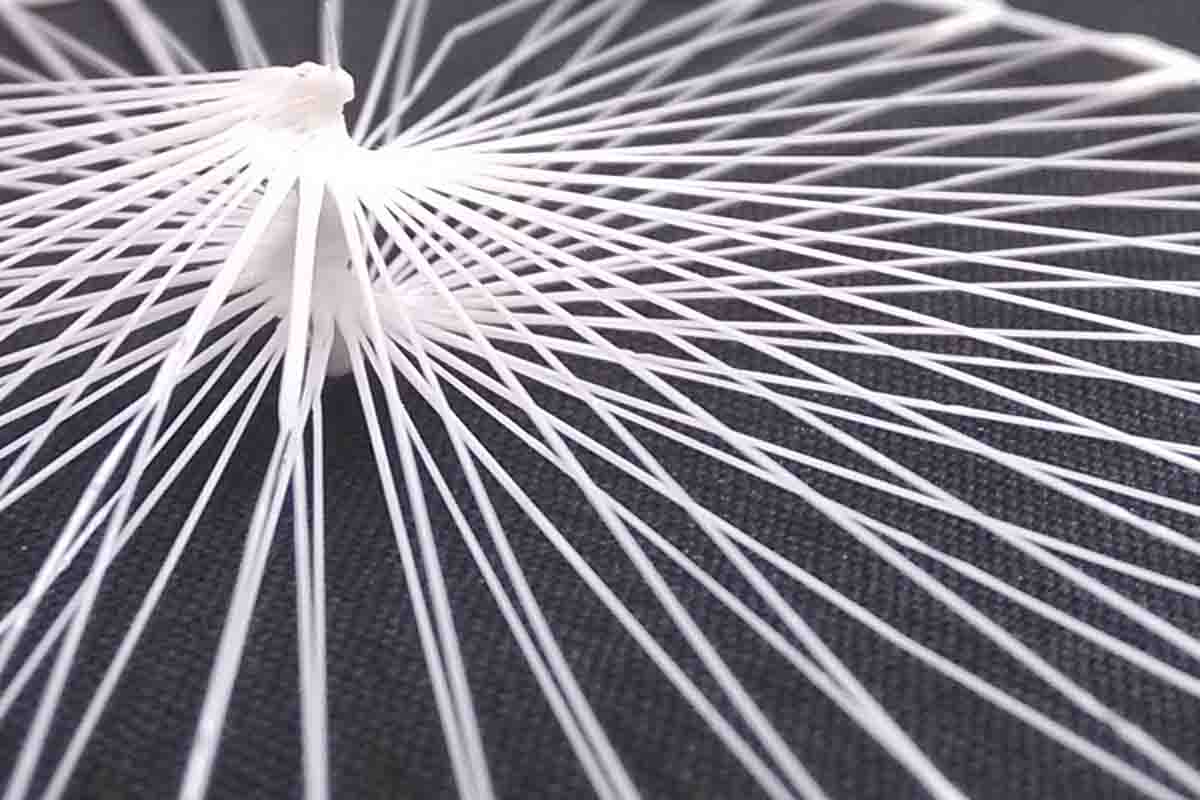
I abandoned catenary curves and started seeing how thin I could make the strands while still building out of the XY plane. This resulted in a spiraling radial design that formed a support by continuously stacking up layers at the center.
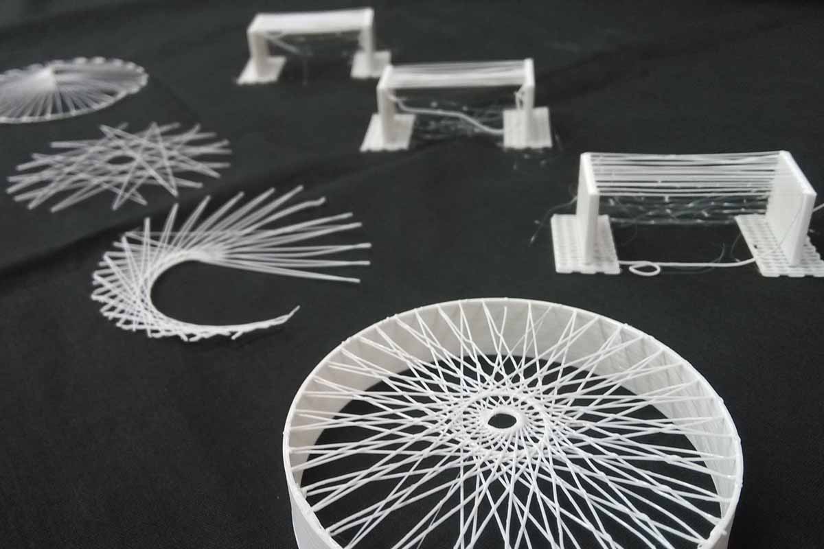
A subset of some of the better results after dozens of failed tests.
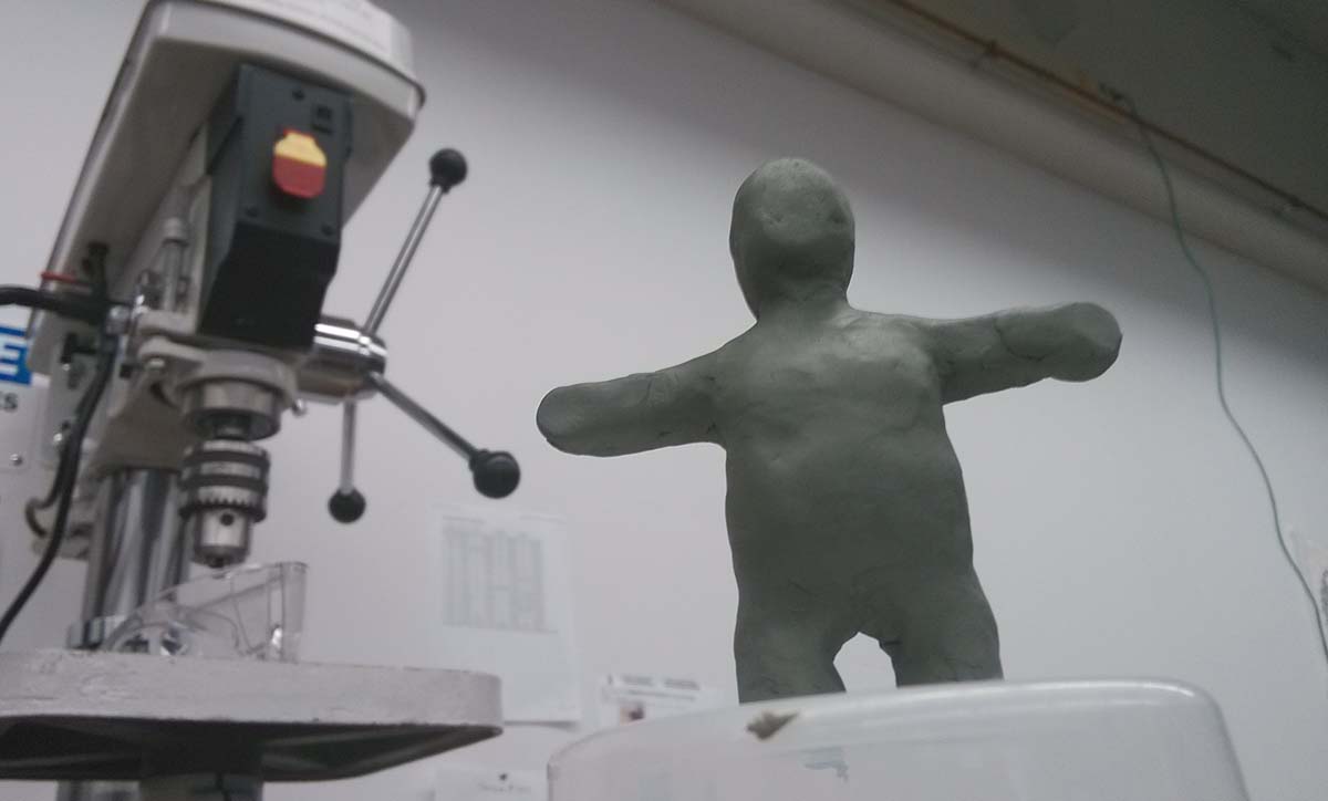
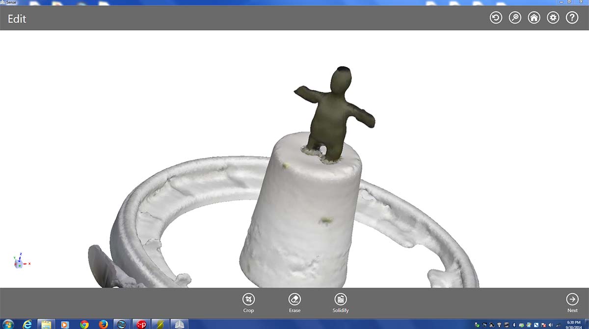
For the 3D scanning exercise, I quickly modeled a humanoid figure out of clay and scanned it with the Sense 3D scanner. Clay seems to be a relatively easy material to scan, which could lend itself to some interesting workflows.