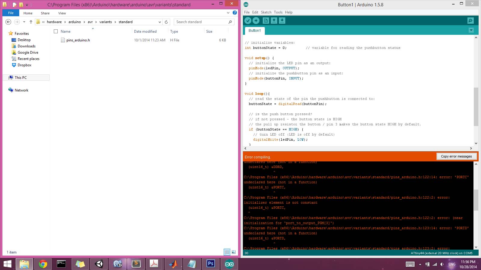
I picked up where I had left off two weeks ago, by trying to find a suitable toolchain for using the Arduino IDE. I had previously successfully programmed the LED blink.c with the make file provided. I just wanted to also set up Arduino IDE as an option, just to have a more comfortable programming environment to more quickly try things out. I'd followed David Mellis' tutorial , but I kept getting errors in the verification phase along the lines of:
avrdude: verification error, first mismatch at byte 0x0040
0x01 != 0x02
avrdude: verification error; content mismatch
The error varies (in terms of byte location) when I edit the boards.txt file. The ATtiny44 segment looks something like:
attiny44-20.upload.tool=arduino:arduinoisp
attiny44-20.name=ATtiny44 (external 20 MHz clock)
attiny44-20.bootloader.low_fuses=0xfe
attiny44-20.bootloader.high_fuses=0xdf
attiny44-20.bootloader.extended_fuses=0xff
attiny44-20.upload.maximum_size=4096
attiny44-20.build.mcu=attiny44
attiny44-20.build.f_cpu=20000000L
attiny44-20.build.core=arduino:arduino
attiny44-20.build.variant=arduino:standard
I found in the data sheet that the Stack Pointer Register should be set to 0x3E (0x5E), though I'm not quite sure what the parentheses mean. In the .make file with which the board was originally programmed (Neil's file) the low fuses were set to 0X5E, though I seem to recall there was some discussion about this in class. In the boards.txt file, if I change 0xfe to either 0x5e or 0x3e, I get content mismatch errors at different bytes. But I don't understand why the bootloader is still of any consequence, as my understanding was that it was used to set the fuses once and that was it. As far as I can tell, everything agrees at 20 MHz.
I never exactly figured this out. I had problems burning the bootloader (couldn't find .tool files), and after wiping and re-following David's tutorial again with the same issues, I realized the only difference was that he's using the 1.0.4 IDE and I was using the most recent release. So I wiped that and installed 1.0.4, and then everything seemed to work (bootloading as well). Seems silly to have to downgrade...I assume the discrepancy has something to do with the directory structure in the 1.5 IDE installing to the Program Files directory, while 1.0 doesn't...? Anyway, I'm more than happy using 1.0.4 for now just to be able to get some results this week.
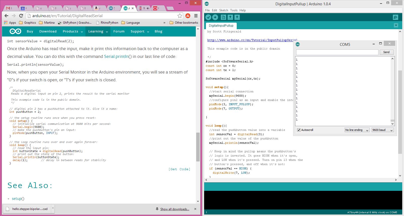
After getting things to work by downgrading Arduino IDE, next on my to-do list was to establish serial communictions with my host computer. I went back and forth between a few sample codes trying to understand why my chip was having issues with the "Serial" command. This is because the ATtiny44 microprocessor is not formatting for serial communication the way that Arduino IDE is expecting it to be. I therefore need to add these lines of code, which specifices the SofwareSerial.h file and tells the IDE which pins should be used for receiving and transmitting (in the case of ATtiny44, pins 0 and 1 respectively):
#include SoftwareSerial.h
const int rx = 0;
const int tx = 1;
SoftwareSerial mySerial(rx,tx);
And then afterwards call any Serial commands using the variable definition "mySerial" instead of just "Serial". For example, Serial.Begin(9600) becomes mySerial.Begin(9600).
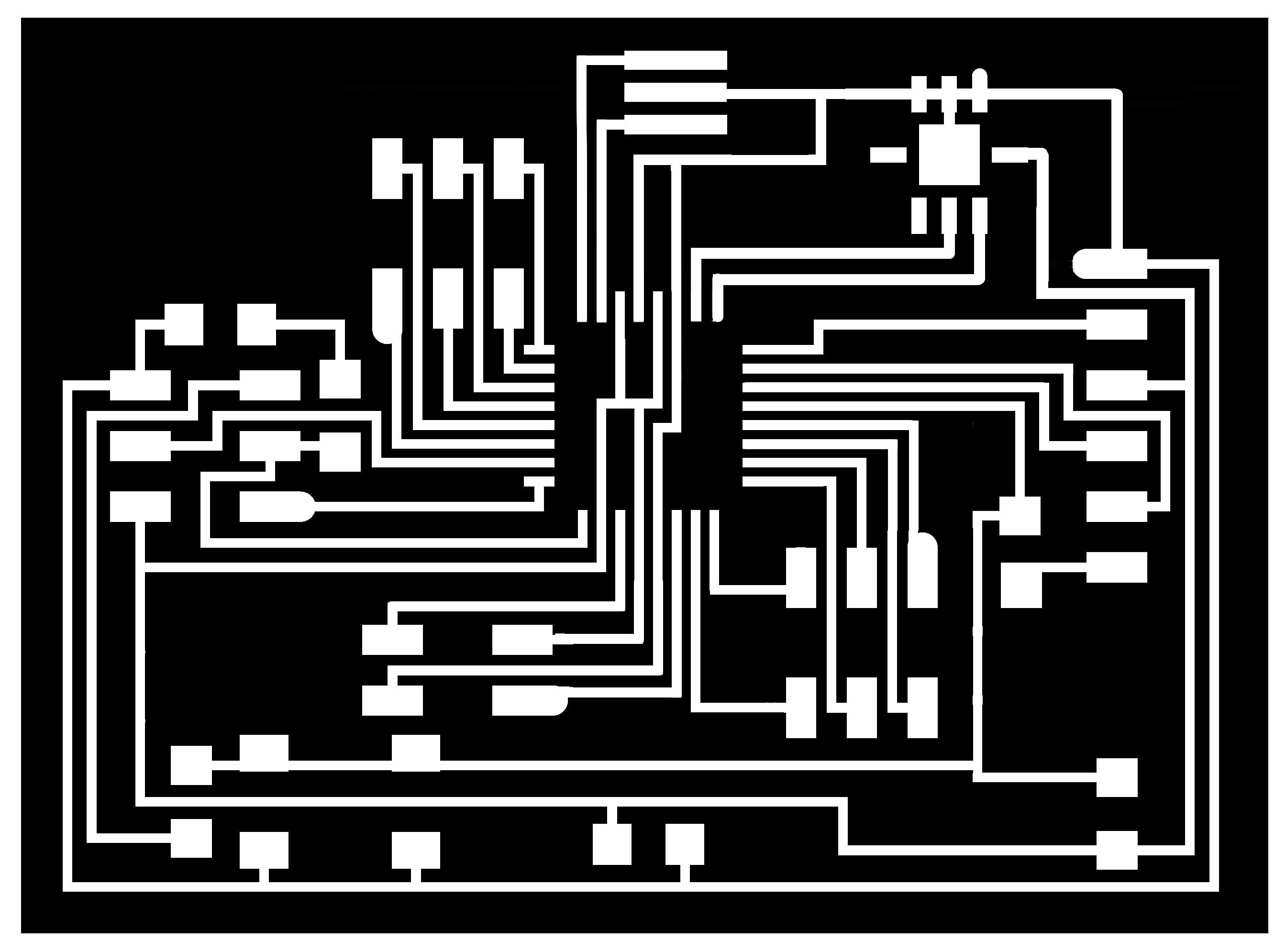
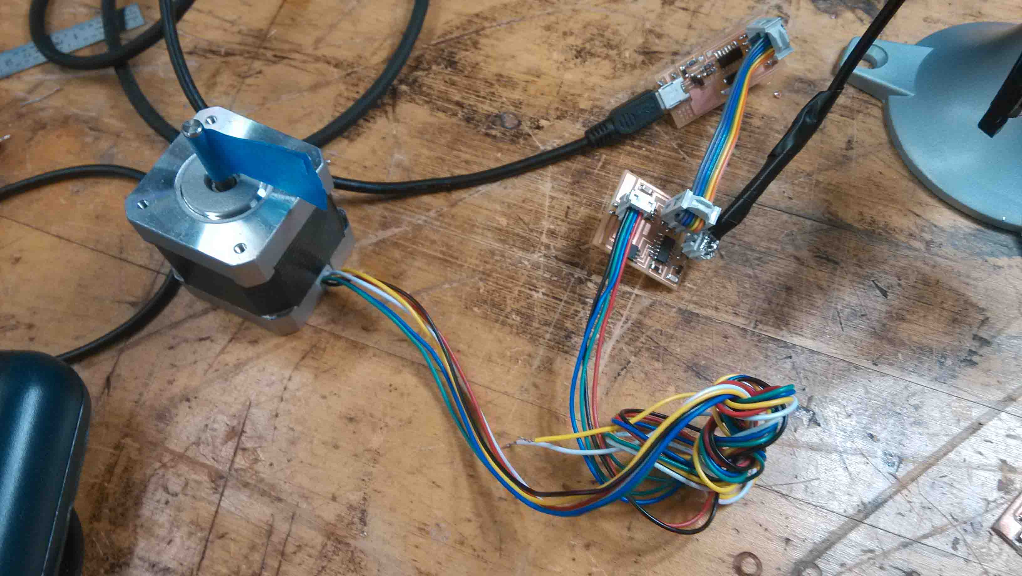
On to the part where we're supposed to design and mill a board with a sensor. I had an hunch that I would need an accelerometer for my final project, and later would need some kind of camera. However, it seems that working with cameras can be quite complex (spanning between various data protocols), and I didn't find many helpful references. So I decided to modify a Fabduino design to include an embedded accelerometer. I figured it would allow me to complete this week's assignment while leaving me enough pins free to add a camera later. I started with Anna's Fabduino Design which pulls out all of the pins for the ATmega328p and added an accelerometer component taken from the in-class example.
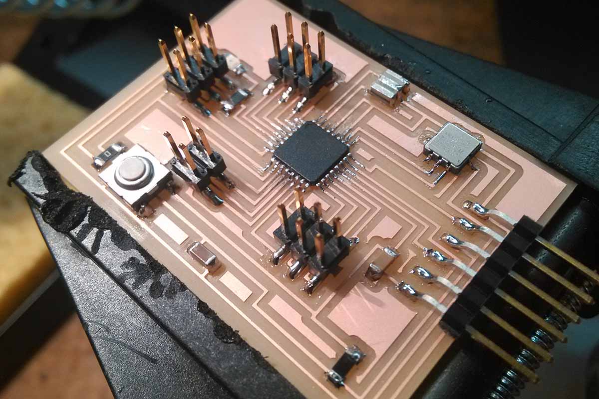
Milled and stuffed board, including the accelerometer in the top right.
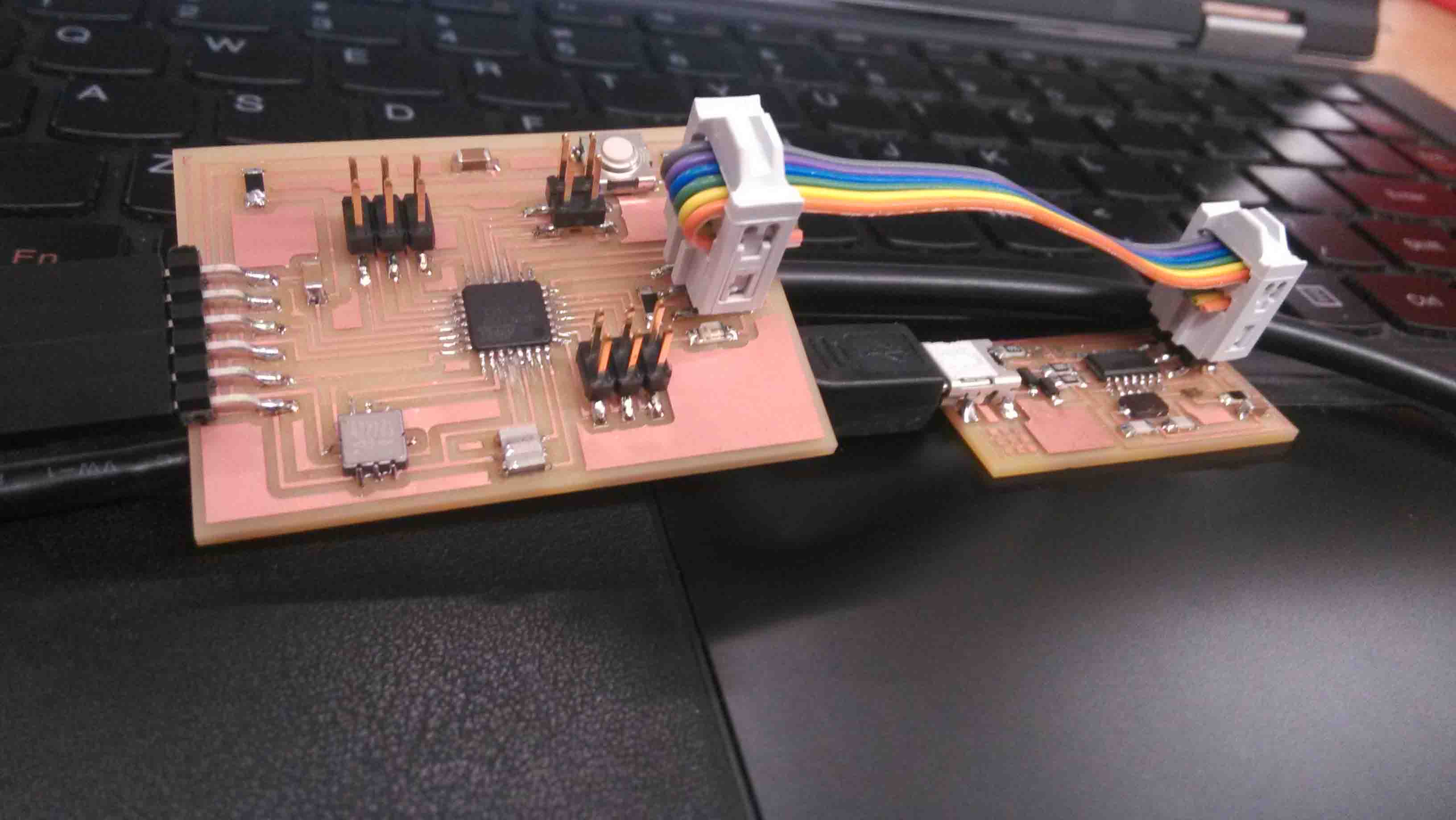
The next step was plugging it into the serial port and programming through the FabISP. Unfortunately, as soon as I plugged it in, it started overheating, which suggested there was a short between GND and VCC somewhere.
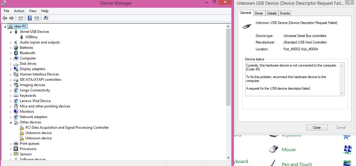
Furthermore, the COM port failed to recognize the device. I made sure I had the correct FTDI drivers and tried to think of anything else that might have gone wrong. I finally decided it was due to the botched solder job on the ATmega328p. Probably a lost cause...I'll need to do it all again, this time more carefully...