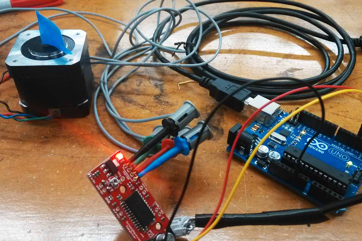
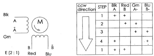
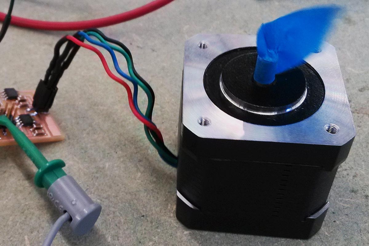
After spending all day Tuesday and Wednesday trying new boards and codes, I was still stuck. Charles Fracchia was super helpful in the diagnostic process, but we still weren't able to get anything running. The motor I used was a bipolar stepper from the inventory (2120479 Jameco part no., RDS-3000 manufacturer no., datasheet It looks identical to the stepper that Neil shows in his hello video. I also used the hello.stepper.bipolar.44 board just for starters. The fuses were set and hello.stepper.bipolar.44.full.c successfully loaded. The board was getting 9V of power. However, it seemed depending of the orientation of the 4 leads of the stepper, the motor either locked up and twitched or did nothing; it didn't make alternating rotations as per the code said it should. To simplify the problem, I edited the code to only rotate CCW (re-loaded the code, the problem persisted). Then, focusing on the CCW loop, it seemed to not correlate with the data sheet information (below).
So I commented out what was written in the C code and replaced it with what seemed to be more in line with the data sheet for this motor (below).
void step_ccw() {
// pulse_ApBm();
// pulse_AmBm();
// pulse_AmBp();
// pulse_ApBp();
pulse_ApBp();
pulse_AmBp();
pulse_AmBm();
pulse_ApBm();
}
However, the same problem persisted. As per the data sheet, Black was paired with Green and Blue was paired with Red (though I also tried rotating the 2x2 header in increments of 90 degrees just to see...same thing...it would twitch when it was in what should be the correct orientation, and do nothing if rotated 90 degrees). Neil made a point of clarifying that wire colors, even when referenced from the correct data sheet, are never guaranteed to actually denote correct pairings. The only way to be sure is to check resistance with an oscilloscope (which I also did, and confirmed that in this case, the pairings from the data sheet were indeed correct).
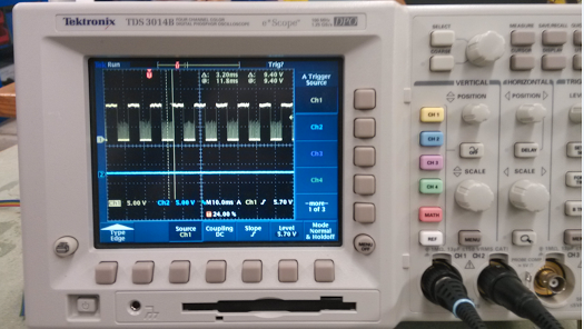
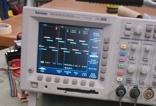
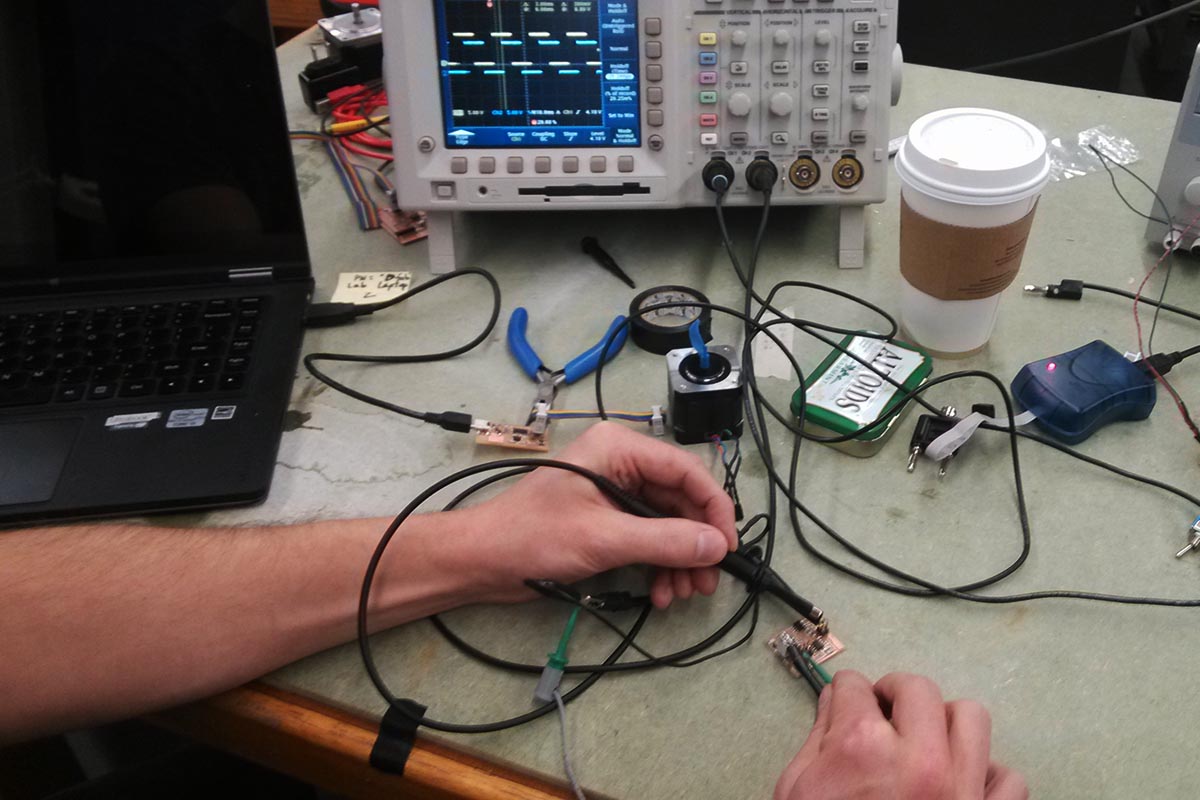
Charles then helped me hook it up to the oscilloscope as he supposed there might be an issue with the signal timing. We routed two channels to opposing pins on the header, and trying different configurations consistently noticed this ghosting effect on one of the channels (below). This seemed to confirm Charles' suspicion about a timing problem. The last thing we tried was changing the PWM_count variable from 100 to 200, but this also didn't have a noticeable effect.

I posted to the class email list, and got some very helpful responses. Matt Edwards suggested using the lab power supply instead of the wall adapter I had been using, just in case the current rating was insufficient. I tried this but didn't see a change.
Charles Guan offered some very illuminating advice:
Looking at your scope picture, the time between step pulses appears to be around 20-30us. This would imply a step frequency of 33,000 Hz, which is far too fast - think about it, at 33,000 hz stepping with a 200-step-per-rev motor, it implies the motor is rotating 10,000 rpm. Our generic iron core stepper motors cannot do this.
Notice the triangular waveform of your step which is on the order or 4-5us long. This is the stepper driver trying to ramp the output voltage up but getting cut off because you end your pulses so soon. I'd recommend increasing your 'pwm counter' to, like 10000 or 20000 and trying again.
So I went back and changed the PWM and step duration variables from Neil's examples. I changed the PWM_count variable from 100 to 10000 as per Charles' suggestion. When I checked on the scope, I was getting wave forms and no longer truncated triangles (although I realize now perhaps I was misusing the scope...I'm still pretty new to this). And anyway, the motor wasn't even twitching anymore.
So I kept trying...I resolved an issue with the power source being unstable, and there seemed to be somewhat of an improvement. When I loaded Neil's hello code, I then got readings like shown below @ 10ms (square waves, but with PWM cycles visible). The 4 pins were all 90 degrees out of phase like they should be. However, the motor still only twitched.
Then as a test, I wrote my own simple stepper function in Arduino IDE, which also provided square waves at 90 degree offsets (image above, also at a 10ms scale). Of course, it lacked the PWM cycles visible in the above image. Should this still be able to drive a stepper? The IN1 and IN2 of the A4952s read a similar PWM pattern as per what should be expected according to the data sheet. At any rate, it still just made the motor twitch. Though according to the resistance measurements, black/green and red/blue should indeed be paired, I continued to try all possible combinations with no luck. I tried checking all the motor lead connections, and tried with others of the same model (Jameco 2120479) with the same results.
After more intensive debugging, I was still preplexed. All of the waveforms of the pins were behaving as the should, all the connections seemed solid. I did notice that the signal coming out of the H-Bridges was a little bit unreliable. It would be correct most of the time, but occasionally would cut out. So I decided to try to remove the H-Bridges with a heat gun.
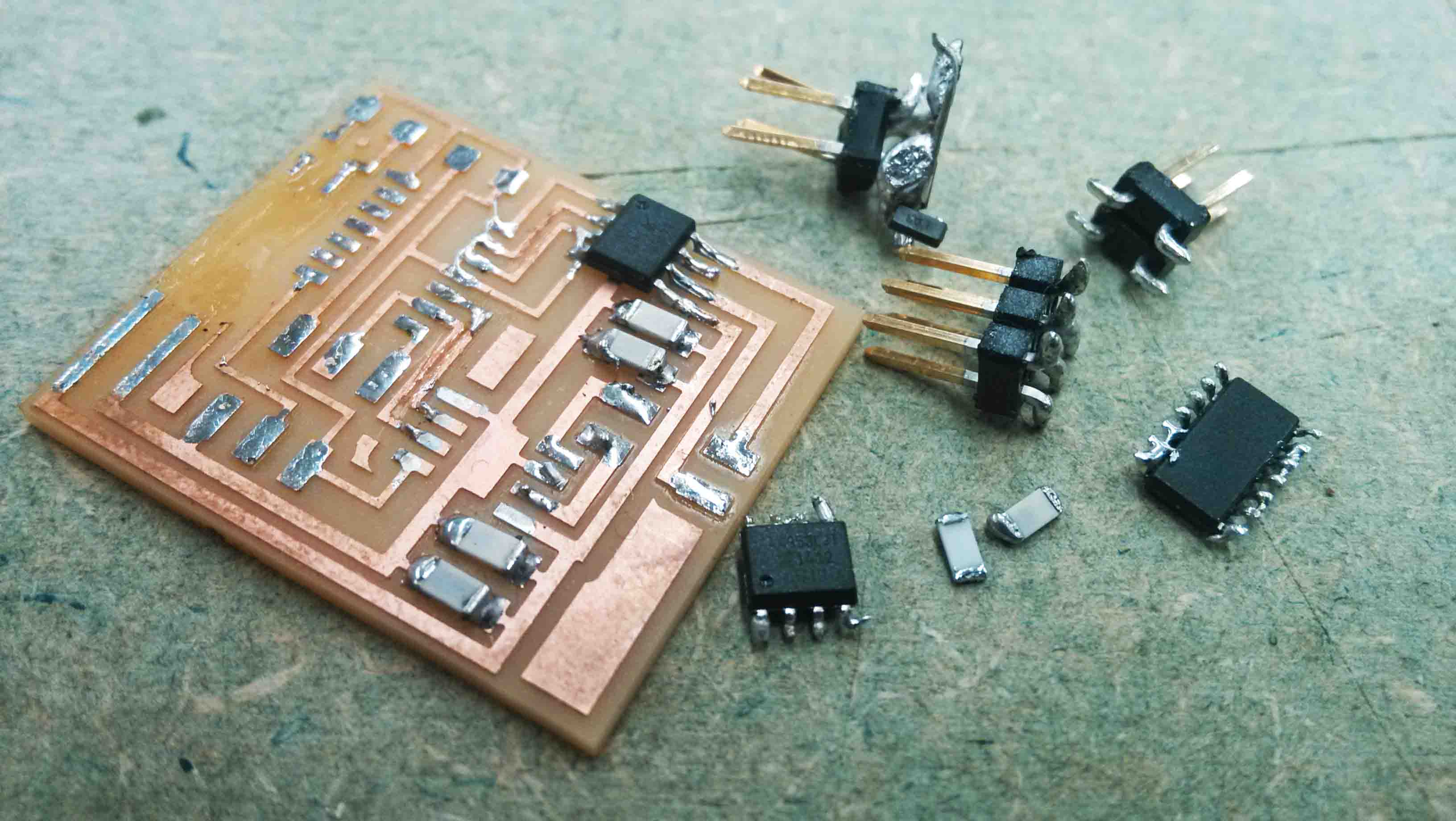
I assumed that if I just held on to the H-Bridge with tweezers and heated up that component, the rest of the chip would fall, leaving only the H-Bridge. Here's a tip: don't try this method. The chip fell just a couple millimeters, but that was enough to shake everything off of the board. That was the nail in the coffin of my bipolar driver.
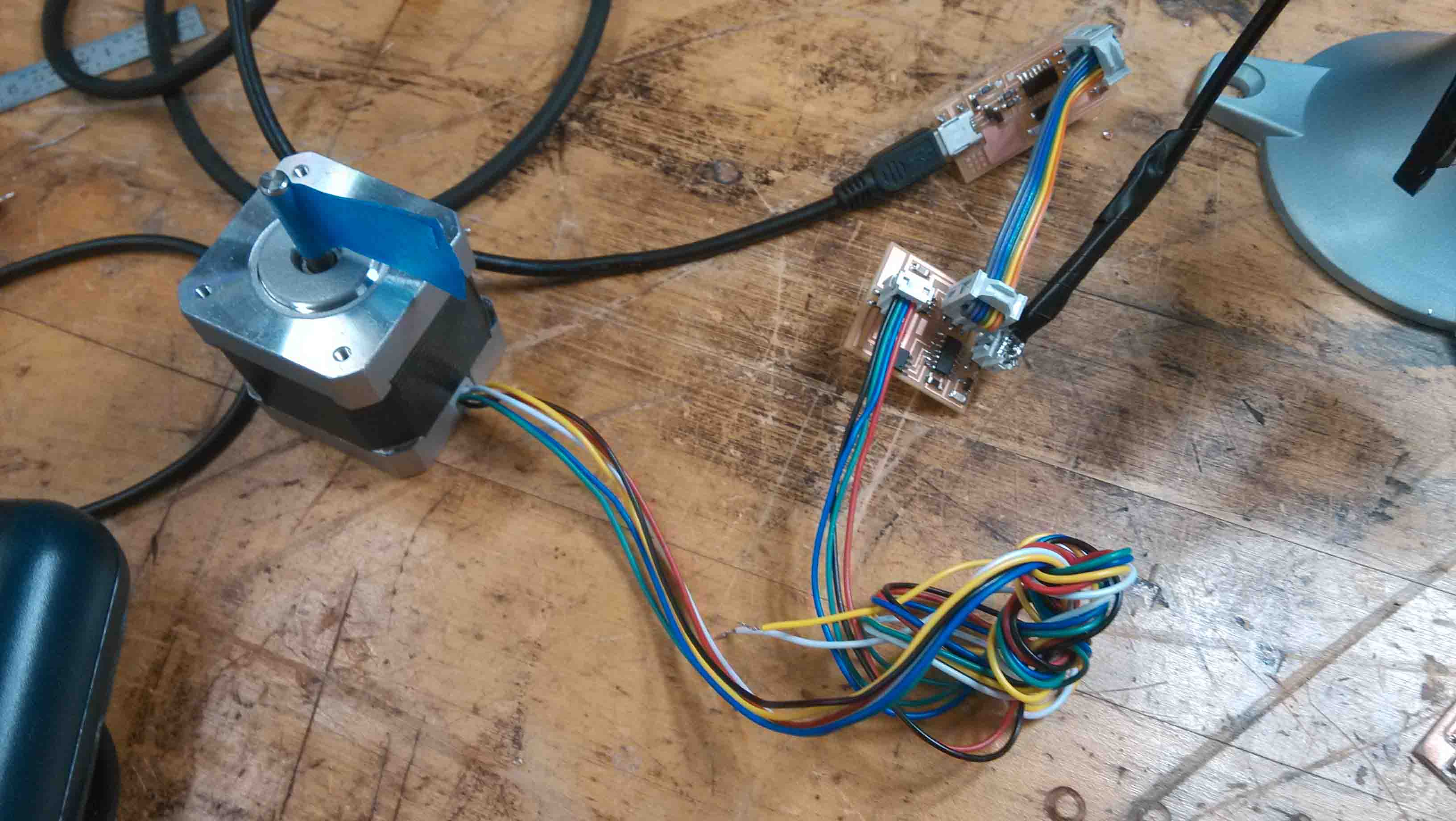
I still don't know what the issue was, but can only assume it was that the H-Bridges burned out. All it took was trying a different board and the motor worked, no problem! I next tried a unipolar driver, which had a whole other set of problems. I was frustrated and annoyed and decided to go with an Easy Driver instead.